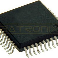
MC68HC705C9ACFBE Freescale Semiconductor, MC68HC705C9ACFBE Datasheet - Page 40

MC68HC705C9ACFBE
Manufacturer Part Number
MC68HC705C9ACFBE
Description
IC MCU 8BIT 44-QFP
Manufacturer
Freescale Semiconductor
Series
HC05r
Datasheet
1.MC705C9ACPE.pdf
(118 pages)
Specifications of MC68HC705C9ACFBE
Core Processor
HC05
Core Size
8-Bit
Speed
2.1MHz
Connectivity
SCI, SPI
Peripherals
POR, WDT
Number Of I /o
24
Program Memory Size
16KB (16K x 8)
Program Memory Type
OTP
Ram Size
352 x 8
Voltage - Supply (vcc/vdd)
3 V ~ 5.5 V
Oscillator Type
Internal
Operating Temperature
-40°C ~ 85°C
Package / Case
44-QFP
Processor Series
HC705C
Core
HC05
Data Bus Width
8 bit
Data Ram Size
352 B
Interface Type
SCI, SPI
Maximum Clock Frequency
2.1 MHz
Number Of Programmable I/os
31
Number Of Timers
1
Maximum Operating Temperature
+ 85 C
Mounting Style
SMD/SMT
Minimum Operating Temperature
- 40 C
On-chip Adc
8 bit
Package
44PQFP
Family Name
HC05
Maximum Speed
2.1 MHz
Operating Supply Voltage
3.3|5 V
Lead Free Status / RoHS Status
Lead free / RoHS Compliant
Eeprom Size
-
Data Converters
-
Lead Free Status / Rohs Status
Details
Available stocks
Company
Part Number
Manufacturer
Quantity
Price
Company:
Part Number:
MC68HC705C9ACFBE
Manufacturer:
FREESCALE
Quantity:
1 827
Company:
Part Number:
MC68HC705C9ACFBE
Manufacturer:
Freescale Semiconductor
Quantity:
10 000
Resets
5.4 Computer Operating Properly (COP) Reset
This device includes a watchdog COP feature which guards against program run-away failures. A timeout
of the computer operating properly (COP) timer generates a COP reset. The COP watchdog is a software
error detection system that automatically times out and resets the MCU if not cleared periodically by a
program sequence.
This device includes two COP types, one for C12A compatibility and the other for C9A compatibility. When
configured as a C9A the COP can be enabled by user software by setting COPE in the C9A COP control
register (C9ACOPCR). When configured as a C12A, the COP is enabled prior to operation by
programming the C12COPE bit in the C12A mask option register (C12MOR). The function and control of
both COPs is detailed below.
40
INTERNAL
ADDRESS
INTERNAL
INTERNAL
CLOCK
(C12A)
RESET
Notes:
BUS 1
RESET
DATA
BUS 1
(C9A)
OSC1
V
2. OSC1 line is not meant to represent frequency. It is only meant to represent time.
1. Internal timing signal and bus information are not available externally.
3. The next rising edge of the internal processor clock following the rising edge of RESET initiates the reset sequence.
4. RESET outputs V
DD
1
2
4064t
4
t
VDDR
CYC
3FFE
NEW
PCH
OL
during 4064 power-on reset cycles when in C9A mode only.
t CYC
MC68HC05C9A Advance Information Data Sheet, Rev. 4.1
3FFF
NEW
PCL
Figure 5-2. Power-On Reset and RESET
DUMMY
NEW
PC
CODE
NEW
OP
PC
3FFE
t
RL
t
RL
3
3
3FFE
3FFE
3FFE
PCH
3FFF
PCL
Freescale Semiconductor
DUMMY
NEW
PC
NEW
CODe
PC
OP


