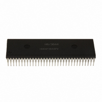
HD64F3644PV Renesas Electronics America, HD64F3644PV Datasheet - Page 171

HD64F3644PV
Manufacturer Part Number
HD64F3644PV
Description
IC H8/3644 MCU FLASH 32K 64SDIP
Manufacturer
Renesas Electronics America
Series
H8® H8/300Lr
Datasheet
1.HD64F3644HV.pdf
(551 pages)
Specifications of HD64F3644PV
Core Processor
H8/300L
Core Size
8-Bit
Speed
8MHz
Connectivity
SCI
Peripherals
PWM, WDT
Number Of I /o
53
Program Memory Size
32KB (32K x 8)
Program Memory Type
FLASH
Ram Size
1K x 8
Voltage - Supply (vcc/vdd)
2.7 V ~ 5.5 V
Data Converters
A/D 8x8b
Oscillator Type
Internal
Operating Temperature
-20°C ~ 75°C
Package / Case
64-SDIP (0.750", 19.05mm)
Lead Free Status / RoHS Status
Lead free / RoHS Compliant
Eeprom Size
-
Available stocks
Company
Part Number
Manufacturer
Quantity
Price
Company:
Part Number:
HD64F3644PV
Manufacturer:
Renesas Electronics America
Quantity:
135
- Current page: 171 of 551
- Download datasheet (4Mb)
Hardware Protection: Hardware protection refers to a state in which programming/erasing of
flash memory is forcibly suspended or disabled. At this time, the flash memory control register
(FLMCR) and erase block register (EBR1 and EBR2) settings are cleared.
Details of the hardware protection states are given below.
Item
Programming
voltage (FV
protect
Reset/standby
protect
Notes: 1. Three modes: program-verify, erase-verify, and prewrite-verify.
6.7.9
If an interrupt is generated while the flash memory is being programmed or erased (while the P or
E bit is set in FLMCR), an operating state may be entered in which the vector will not be read
correctly in the exception handling sequence, resulting in program runaway. All interrupt sources
should therefore be masked to prevent interrupt generation while programming or erasing the flash
memory.
2. All blocks are erase-disabled, and individual block specification is not possible.
3. For details, see section 6.9, Flash Memory Programming and Erasing Precautions.
4. For details, see AC Characteristics in section 13, Electrical Characteristics.
Interrupt Handling during Flash Memory Programming/Erasing
PP
)
Description
When 12 V is not being applied to the
FV
are initialized, and the program/erase-
protected state is entered. To obtain
this protection, the V
not exceed the V
voltage. *
In a reset, (including a watchdog timer
reset), and in sleep, subsleep, watch,
and standby mode, FLMCR, EBR1,
and EBR2 are initialized, and the
program/erase-protected state is
entered. In a reset via the RES pin, the
reset state is not reliably entered
unless the RES pin is held low for at
least 20 ms (oscillation settling time) *
after powering on. In the case of a
reset during operation, the RES pin
must be held low for a minimum of 10
system clock cycles (10 ).
PP
pin, FLMCR, EBR1, and EBR2
3
CC
power supply
PP
voltage should
4
Rev. 6.00 Sep 12, 2006 page 149 of 526
Program
Disabled
Disabled
Erase
Disabled *
Disabled *
Functions
REJ09B0326-0600
2
2
Section 6 ROM
Verify *
Disabled
Disabled
1
Related parts for HD64F3644PV
Image
Part Number
Description
Manufacturer
Datasheet
Request
R

Part Number:
Description:
(HD64 Series) Hitachi Single-Chip Microcomputer
Manufacturer:
Hitachi Semiconductor
Datasheet:

Part Number:
Description:
KIT STARTER FOR M16C/29
Manufacturer:
Renesas Electronics America
Datasheet:

Part Number:
Description:
KIT STARTER FOR R8C/2D
Manufacturer:
Renesas Electronics America
Datasheet:

Part Number:
Description:
R0K33062P STARTER KIT
Manufacturer:
Renesas Electronics America
Datasheet:

Part Number:
Description:
KIT STARTER FOR R8C/23 E8A
Manufacturer:
Renesas Electronics America
Datasheet:

Part Number:
Description:
KIT STARTER FOR R8C/25
Manufacturer:
Renesas Electronics America
Datasheet:

Part Number:
Description:
KIT STARTER H8S2456 SHARPE DSPLY
Manufacturer:
Renesas Electronics America
Datasheet:

Part Number:
Description:
KIT STARTER FOR R8C38C
Manufacturer:
Renesas Electronics America
Datasheet:

Part Number:
Description:
KIT STARTER FOR R8C35C
Manufacturer:
Renesas Electronics America
Datasheet:

Part Number:
Description:
KIT STARTER FOR R8CL3AC+LCD APPS
Manufacturer:
Renesas Electronics America
Datasheet:

Part Number:
Description:
KIT STARTER FOR RX610
Manufacturer:
Renesas Electronics America
Datasheet:

Part Number:
Description:
KIT STARTER FOR R32C/118
Manufacturer:
Renesas Electronics America
Datasheet:

Part Number:
Description:
KIT DEV RSK-R8C/26-29
Manufacturer:
Renesas Electronics America
Datasheet:

Part Number:
Description:
KIT STARTER FOR SH7124
Manufacturer:
Renesas Electronics America
Datasheet:

Part Number:
Description:
KIT STARTER FOR H8SX/1622
Manufacturer:
Renesas Electronics America
Datasheet:


