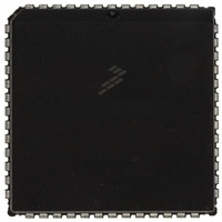
MC68HC711E9CFNE2 Freescale Semiconductor, MC68HC711E9CFNE2 Datasheet - Page 286

MC68HC711E9CFNE2
Manufacturer Part Number
MC68HC711E9CFNE2
Description
IC MCU 8BIT 512RAM 52-PLC
Manufacturer
Freescale Semiconductor
Series
HC11r
Datasheet
1.MC68HC711E9CFNE3.pdf
(336 pages)
Specifications of MC68HC711E9CFNE2
Core Processor
HC11
Core Size
8-Bit
Speed
2MHz
Connectivity
SCI, SPI
Peripherals
POR, WDT
Number Of I /o
38
Program Memory Size
12KB (12K x 8)
Program Memory Type
OTP
Eeprom Size
512 x 8
Ram Size
512 x 8
Voltage - Supply (vcc/vdd)
4.5 V ~ 5.5 V
Data Converters
A/D 8x8b
Oscillator Type
Internal
Operating Temperature
-40°C ~ 85°C
Package / Case
52-PLCC
Processor Series
HC711E
Core
HC11
Data Bus Width
8 bit
Data Ram Size
512 B
Interface Type
SCI, SPI
Maximum Clock Frequency
2 MHz
Number Of Programmable I/os
38
Number Of Timers
8
Maximum Operating Temperature
+ 85 C
Mounting Style
SMD/SMT
Minimum Operating Temperature
- 40 C
On-chip Adc
8 bit
Lead Free Status / RoHS Status
Lead free / RoHS Compliant
Available stocks
Company
Part Number
Manufacturer
Quantity
Price
Company:
Part Number:
MC68HC711E9CFNE2
Manufacturer:
TE
Quantity:
12 000
Company:
Part Number:
MC68HC711E9CFNE2
Manufacturer:
FREESCAL
Quantity:
5 530
- Current page: 286 of 336
- Download datasheet (4Mb)
Application Note
The SCI receiver and transmitter are enabled. The receiver is required
by the bootloading process, and the transmitter is used to transmit data
back to the host computer for optional verification. The last item in the
initialization is to set an intercharacter delay constant used to terminate
the download when the host computer stops sending data to the
MC68HC711E9. This delay constant is stored in the timer output
compare 1 (TOC1) register, but the on-chip timer is not used in the
bootloader program. This example illustrates the extreme measures
used in the bootloader firmware to minimize memory usage. However,
such measures are not usually considered good programming technique
because they are misleading to someone trying to understand the
program or use it as an example.
After initialization, a break character is transmitted [3] by the SCI. By
connecting the TxD pin to the RxD pin (with a pullup because of port D
wired-OR mode), this break will be received as a $00 character and
cause an immediate jump [4] to the start of the on-chip EEPROM ($B600
in the MC68HC711E9). This feature is useful to pass control to a
program in EEPROM essentially from reset. Refer to
Common
Bootstrap Mode Problems
before using this feature.
If the first character is received as $FF, the baud rate is assumed to be
the default rate (7812 baud at a 2-MHz E-clock rate). If $FF was sent at
1200 baud by the host, the SCI will receive the character as $E0 or $C0
because of the baud rate mismatch, and the bootloader will switch to
1200 baud [5] for the rest of the download operation. When the baud rate
is switched to 1200 baud, the delay constant used to monitor the
intercharacter delay also must be changed to reflect the new character
time.
At [6], the Y index register is initialized to $0000 to point to the start of
on-chip RAM. The index register Y is used to keep track of where the
next received data byte will be stored in RAM. The main loop for loading
begins at [7].
The number of data bytes in the downloaded program can be any
number between 0 and 512 bytes (the size of on-chip RAM). This
procedure is called "variable-length download" and is accomplished by
ending the download sequence when an idle time of at least four
character times occurs after the last character to be downloaded. In
AN1060 — Rev. 1.0
286
MOTOROLA
Related parts for MC68HC711E9CFNE2
Image
Part Number
Description
Manufacturer
Datasheet
Request
R

Part Number:
Description:
APPENDIX A ELECTRICAL CHARACTERISTICS
Manufacturer:
FREESCALE [Freescale Semiconductor, Inc]
Datasheet:
Part Number:
Description:
Manufacturer:
Freescale Semiconductor, Inc
Datasheet:
Part Number:
Description:
Manufacturer:
Freescale Semiconductor, Inc
Datasheet:
Part Number:
Description:
Manufacturer:
Freescale Semiconductor, Inc
Datasheet:
Part Number:
Description:
Manufacturer:
Freescale Semiconductor, Inc
Datasheet:
Part Number:
Description:
Manufacturer:
Freescale Semiconductor, Inc
Datasheet:
Part Number:
Description:
Manufacturer:
Freescale Semiconductor, Inc
Datasheet:
Part Number:
Description:
Manufacturer:
Freescale Semiconductor, Inc
Datasheet:
Part Number:
Description:
Manufacturer:
Freescale Semiconductor, Inc
Datasheet:
Part Number:
Description:
Manufacturer:
Freescale Semiconductor, Inc
Datasheet:
Part Number:
Description:
Manufacturer:
Freescale Semiconductor, Inc
Datasheet:
Part Number:
Description:
Manufacturer:
Freescale Semiconductor, Inc
Datasheet:
Part Number:
Description:
Manufacturer:
Freescale Semiconductor, Inc
Datasheet:
Part Number:
Description:
Manufacturer:
Freescale Semiconductor, Inc
Datasheet:
Part Number:
Description:
Manufacturer:
Freescale Semiconductor, Inc
Datasheet:


