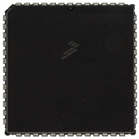
MC68HC711E9CFNE2 Freescale Semiconductor, MC68HC711E9CFNE2 Datasheet - Page 55

MC68HC711E9CFNE2
Manufacturer Part Number
MC68HC711E9CFNE2
Description
IC MCU 8BIT 512RAM 52-PLC
Manufacturer
Freescale Semiconductor
Series
HC11r
Datasheet
1.MC68HC711E9CFNE3.pdf
(336 pages)
Specifications of MC68HC711E9CFNE2
Core Processor
HC11
Core Size
8-Bit
Speed
2MHz
Connectivity
SCI, SPI
Peripherals
POR, WDT
Number Of I /o
38
Program Memory Size
12KB (12K x 8)
Program Memory Type
OTP
Eeprom Size
512 x 8
Ram Size
512 x 8
Voltage - Supply (vcc/vdd)
4.5 V ~ 5.5 V
Data Converters
A/D 8x8b
Oscillator Type
Internal
Operating Temperature
-40°C ~ 85°C
Package / Case
52-PLCC
Processor Series
HC711E
Core
HC11
Data Bus Width
8 bit
Data Ram Size
512 B
Interface Type
SCI, SPI
Maximum Clock Frequency
2 MHz
Number Of Programmable I/os
38
Number Of Timers
8
Maximum Operating Temperature
+ 85 C
Mounting Style
SMD/SMT
Minimum Operating Temperature
- 40 C
On-chip Adc
8 bit
Lead Free Status / RoHS Status
Lead free / RoHS Compliant
Available stocks
Company
Part Number
Manufacturer
Quantity
Price
Company:
Part Number:
MC68HC711E9CFNE2
Manufacturer:
TE
Quantity:
12 000
Company:
Part Number:
MC68HC711E9CFNE2
Manufacturer:
FREESCAL
Quantity:
5 530
- Current page: 55 of 336
- Download datasheet (4Mb)
3.6.2 Direct
3.6.3 Extended
3.6.4 Indexed
3.6.5 Inherent
M68HC11E Family — Rev. 3.2
MOTOROLA
In the direct addressing mode, the low-order byte of the operand
address is contained in a single byte following the opcode, and the
high-order byte of the address is assumed to be $00. Addresses
$00–$FF are thus accessed directly, using 2-byte instructions.
Execution time is reduced by eliminating the additional memory access
required for the high-order address byte. In most applications, this
256-byte area is reserved for frequently referenced data. In M68HC11
MCUs, the memory map can be configured for combinations of internal
registers, RAM, or external memory to occupy these addresses.
In the extended addressing mode, the effective address of the argument
is contained in two bytes following the opcode byte. These are 3-byte
instructions (or 4-byte instructions if a prebyte is required). One or two
bytes are needed for the opcode and two for the effective address.
In the indexed addressing mode, an 8-bit unsigned offset contained in
the instruction is added to the value contained in an index register (IX or
IY). The sum is the effective address. This addressing mode allows
referencing any memory location in the 64-Kbyte address space. These
are 2- to 5-byte instructions, depending on whether or not a prebyte is
required.
In the inherent addressing mode, all the information necessary to
execute the instruction is contained in the opcode. Operations that use
only the index registers or accumulators, as well as control instructions
with no arguments, are included in this addressing mode. These are
1- or 2-byte instructions.
Central Processor Unit (CPU)
Central Processor Unit (CPU)
Addressing Modes
Technical Data
55
Related parts for MC68HC711E9CFNE2
Image
Part Number
Description
Manufacturer
Datasheet
Request
R

Part Number:
Description:
APPENDIX A ELECTRICAL CHARACTERISTICS
Manufacturer:
FREESCALE [Freescale Semiconductor, Inc]
Datasheet:
Part Number:
Description:
Manufacturer:
Freescale Semiconductor, Inc
Datasheet:
Part Number:
Description:
Manufacturer:
Freescale Semiconductor, Inc
Datasheet:
Part Number:
Description:
Manufacturer:
Freescale Semiconductor, Inc
Datasheet:
Part Number:
Description:
Manufacturer:
Freescale Semiconductor, Inc
Datasheet:
Part Number:
Description:
Manufacturer:
Freescale Semiconductor, Inc
Datasheet:
Part Number:
Description:
Manufacturer:
Freescale Semiconductor, Inc
Datasheet:
Part Number:
Description:
Manufacturer:
Freescale Semiconductor, Inc
Datasheet:
Part Number:
Description:
Manufacturer:
Freescale Semiconductor, Inc
Datasheet:
Part Number:
Description:
Manufacturer:
Freescale Semiconductor, Inc
Datasheet:
Part Number:
Description:
Manufacturer:
Freescale Semiconductor, Inc
Datasheet:
Part Number:
Description:
Manufacturer:
Freescale Semiconductor, Inc
Datasheet:
Part Number:
Description:
Manufacturer:
Freescale Semiconductor, Inc
Datasheet:
Part Number:
Description:
Manufacturer:
Freescale Semiconductor, Inc
Datasheet:
Part Number:
Description:
Manufacturer:
Freescale Semiconductor, Inc
Datasheet:


