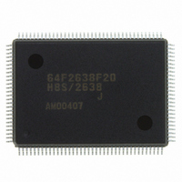
HD64F2638F20J Renesas Electronics America, HD64F2638F20J Datasheet - Page 613

HD64F2638F20J
Manufacturer Part Number
HD64F2638F20J
Description
IC H8S MCU FLASH 256K 128-QFP
Manufacturer
Renesas Electronics America
Series
H8® H8S/2600r
Specifications of HD64F2638F20J
Core Processor
H8S/2600
Core Size
16-Bit
Speed
20MHz
Connectivity
CAN, SCI, SmartCard
Peripherals
Motor Control PWM, POR, PWM, WDT
Number Of I /o
72
Program Memory Size
256KB (256K x 8)
Program Memory Type
FLASH
Ram Size
16K x 8
Voltage - Supply (vcc/vdd)
4.5 V ~ 5.5 V
Data Converters
A/D 12x10b; D/A 2x8b
Oscillator Type
Internal
Operating Temperature
-40°C ~ 85°C
Package / Case
128-QFP
Lead Free Status / RoHS Status
Contains lead / RoHS non-compliant
Eeprom Size
-
Available stocks
Company
Part Number
Manufacturer
Quantity
Price
Company:
Part Number:
HD64F2638F20J
Manufacturer:
PENESAS
Quantity:
252
- Current page: 613 of 1512
- Download datasheet (9Mb)
H8S/2639, H8S/2638, H8S/2636,
H8S/2630, H8S/2635 Group
Bit 2—Bus Busy (BBSY): The BBSY flag can be read to check whether the I
is busy or free. In master mode, this bit is also used to issue start and stop conditions.
A high-to-low transition of SDA while SCL is high is recognized as a start condition, setting
BBSY to 1. A low-to-high transition of SDA while SCL is high is recognized as a stop condition,
clearing BBSY to 0.
To issue a start condition, use a MOV instruction to write 1 in BBSY and 0 in SCP. A retransmit
start condition is issued in the same way. To issue a stop condition, use a MOV instruction to
write 0 in BBSY and 0 in SCP. It is not possible to write to BBSY in slave mode; the I
interface must be set to master transmit mode before issuing a start condition. MST and TRS
should both be set to 1 before writing 1 in BBSY and 0 in SCP.
Bit 2
BBSY
0
1
Bit 1—I
has issued an interrupt request to the CPU. IRIC is set to 1 at the end of a data transfer, when a
slave address or general call address is detected in slave receive mode, when bus arbitration is lost
in master transmit mode, and when a stop condition is detected. IRIC is set at different times
depending on the FS bit in SAR and the WAIT bit in ICMR. See section 15.3.7, IRIC Setting
Timing and SCL Control. The conditions under which IRIC is set also differ depending on the
setting of the ACKE bit in ICCR.
IRIC is cleared by reading IRIC after it has been set to 1, then writing 0 in IRIC.
When the DTC is used, IRIC is cleared automatically and transfer can be performed continuously
without CPU intervention.
REJ09B0103-0800 Rev. 8.00
May 28, 2010
2
C Bus Interface Interrupt Request Flag (IRIC): Indicates that the I
Description
Bus is free
[Clearing condition]
•
Bus is busy
[Setting condition]
•
When a stop condition is detected
When a start condition is detected
(Only for the H8S/2638, H8S/2639, and H8S/2630)
Section 15 I
2
C bus (SCL, SDA)
2
2
C bus interface
C Bus Interface [Option]
(Initial value)
Page 563 of 1458
2
C bus
Related parts for HD64F2638F20J
Image
Part Number
Description
Manufacturer
Datasheet
Request
R

Part Number:
Description:
KIT STARTER FOR M16C/29
Manufacturer:
Renesas Electronics America
Datasheet:

Part Number:
Description:
KIT STARTER FOR R8C/2D
Manufacturer:
Renesas Electronics America
Datasheet:

Part Number:
Description:
R0K33062P STARTER KIT
Manufacturer:
Renesas Electronics America
Datasheet:

Part Number:
Description:
KIT STARTER FOR R8C/23 E8A
Manufacturer:
Renesas Electronics America
Datasheet:

Part Number:
Description:
KIT STARTER FOR R8C/25
Manufacturer:
Renesas Electronics America
Datasheet:

Part Number:
Description:
KIT STARTER H8S2456 SHARPE DSPLY
Manufacturer:
Renesas Electronics America
Datasheet:

Part Number:
Description:
KIT STARTER FOR R8C38C
Manufacturer:
Renesas Electronics America
Datasheet:

Part Number:
Description:
KIT STARTER FOR R8C35C
Manufacturer:
Renesas Electronics America
Datasheet:

Part Number:
Description:
KIT STARTER FOR R8CL3AC+LCD APPS
Manufacturer:
Renesas Electronics America
Datasheet:

Part Number:
Description:
KIT STARTER FOR RX610
Manufacturer:
Renesas Electronics America
Datasheet:

Part Number:
Description:
KIT STARTER FOR R32C/118
Manufacturer:
Renesas Electronics America
Datasheet:

Part Number:
Description:
KIT DEV RSK-R8C/26-29
Manufacturer:
Renesas Electronics America
Datasheet:

Part Number:
Description:
KIT STARTER FOR SH7124
Manufacturer:
Renesas Electronics America
Datasheet:

Part Number:
Description:
KIT STARTER FOR H8SX/1622
Manufacturer:
Renesas Electronics America
Datasheet:


