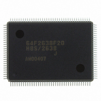
HD64F2638F20J Renesas Electronics America, HD64F2638F20J Datasheet - Page 704

HD64F2638F20J
Manufacturer Part Number
HD64F2638F20J
Description
IC H8S MCU FLASH 256K 128-QFP
Manufacturer
Renesas Electronics America
Series
H8® H8S/2600r
Specifications of HD64F2638F20J
Core Processor
H8S/2600
Core Size
16-Bit
Speed
20MHz
Connectivity
CAN, SCI, SmartCard
Peripherals
Motor Control PWM, POR, PWM, WDT
Number Of I /o
72
Program Memory Size
256KB (256K x 8)
Program Memory Type
FLASH
Ram Size
16K x 8
Voltage - Supply (vcc/vdd)
4.5 V ~ 5.5 V
Data Converters
A/D 12x10b; D/A 2x8b
Oscillator Type
Internal
Operating Temperature
-40°C ~ 85°C
Package / Case
128-QFP
Lead Free Status / RoHS Status
Contains lead / RoHS non-compliant
Eeprom Size
-
Available stocks
Company
Part Number
Manufacturer
Quantity
Price
Company:
Part Number:
HD64F2638F20J
Manufacturer:
PENESAS
Quantity:
252
- Current page: 704 of 1512
- Download datasheet (9Mb)
Section 16 Controller Area Network (HCAN)
16.3.2
After a hardware reset, the following initialization processing should be carried out:
• Clearing of IRR0 bit in interrupt register (IRR)
• Bit rate setting
• Mailbox transmit/receive settings
• Mailbox (RAM) initialization
• Message transmission method setting
These initial settings must be made while the HCAN is in bit configuration mode. Configuration
mode is a state in which the reset request bit (MCR0) in the master control register (MCR) is 1 and
the reset status bit in the general status register (GSR) is also 1 (GSR3 = 1). Configuration mode is
exited by clearing the reset request bit in MCR to 0; when MCR0 is cleared to 0, the HCAN
automatically clears the reset state bit (GSR3) in the general status register (GSR). The power-up
sequence then begins, and communication with the CAN bus is possible as soon as the sequence
ends. The power-up sequence consists of the detection of 11 consecutive recessive bits.
IRR0 Clearing: The reset interrupt flag (IRR0) is always set after a reset or recovery from
software standby mode. As an HCAN interrupt is initiated immediately when interrupts are
enabled, IRR0 should be cleared.
Bit Rate and Bit Timing Settings: As bit rate settings, a baud rate setting and bit timing setting
must be made each time a CAN node begins communication. The baud rate and bit timing settings
are made in the bit configuration register (BCR).
a. Note
Page 654 of 1458
BCR can be written to at all times, but should only be modified in configuration mode.
Settings should be made so that all CAN controllers connected to the CAN bus have the same
baud rate and bit width.
Limits for the settable variables (TSEG1, TSEG2, BRP, sample point, and SJW) are shown in
table 16-3.
Initialization after Hardware Reset
H8S/2639, H8S/2638, H8S/2636,
REJ09B0103-0800 Rev. 8.00
H8S/2630, H8S/2635 Group
May 28, 2010
Related parts for HD64F2638F20J
Image
Part Number
Description
Manufacturer
Datasheet
Request
R

Part Number:
Description:
KIT STARTER FOR M16C/29
Manufacturer:
Renesas Electronics America
Datasheet:

Part Number:
Description:
KIT STARTER FOR R8C/2D
Manufacturer:
Renesas Electronics America
Datasheet:

Part Number:
Description:
R0K33062P STARTER KIT
Manufacturer:
Renesas Electronics America
Datasheet:

Part Number:
Description:
KIT STARTER FOR R8C/23 E8A
Manufacturer:
Renesas Electronics America
Datasheet:

Part Number:
Description:
KIT STARTER FOR R8C/25
Manufacturer:
Renesas Electronics America
Datasheet:

Part Number:
Description:
KIT STARTER H8S2456 SHARPE DSPLY
Manufacturer:
Renesas Electronics America
Datasheet:

Part Number:
Description:
KIT STARTER FOR R8C38C
Manufacturer:
Renesas Electronics America
Datasheet:

Part Number:
Description:
KIT STARTER FOR R8C35C
Manufacturer:
Renesas Electronics America
Datasheet:

Part Number:
Description:
KIT STARTER FOR R8CL3AC+LCD APPS
Manufacturer:
Renesas Electronics America
Datasheet:

Part Number:
Description:
KIT STARTER FOR RX610
Manufacturer:
Renesas Electronics America
Datasheet:

Part Number:
Description:
KIT STARTER FOR R32C/118
Manufacturer:
Renesas Electronics America
Datasheet:

Part Number:
Description:
KIT DEV RSK-R8C/26-29
Manufacturer:
Renesas Electronics America
Datasheet:

Part Number:
Description:
KIT STARTER FOR SH7124
Manufacturer:
Renesas Electronics America
Datasheet:

Part Number:
Description:
KIT STARTER FOR H8SX/1622
Manufacturer:
Renesas Electronics America
Datasheet:


