ATMEGA88V-10MU Atmel, ATMEGA88V-10MU Datasheet - Page 88
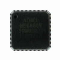
ATMEGA88V-10MU
Manufacturer Part Number
ATMEGA88V-10MU
Description
IC AVR MCU 8K 10MHZ 1.8V 32-QFN
Manufacturer
Atmel
Series
AVR® ATmegar
Specifications of ATMEGA88V-10MU
Core Processor
AVR
Core Size
8-Bit
Speed
10MHz
Connectivity
I²C, SPI, UART/USART
Peripherals
Brown-out Detect/Reset, POR, PWM, WDT
Number Of I /o
23
Program Memory Size
8KB (4K x 16)
Program Memory Type
FLASH
Eeprom Size
512 x 8
Ram Size
1K x 8
Voltage - Supply (vcc/vdd)
1.8 V ~ 5.5 V
Data Converters
A/D 8x10b
Oscillator Type
Internal
Operating Temperature
-40°C ~ 85°C
Package / Case
32-VQFN Exposed Pad, 32-HVQFN, 32-SQFN, 32-DHVQFN
Processor Series
ATMEGA8x
Core
AVR8
Data Bus Width
8 bit
Data Ram Size
1 KB
Interface Type
2-Wire, SPI, USART, Serial
Maximum Clock Frequency
20 MHz
Number Of Programmable I/os
23
Number Of Timers
3 bit
Operating Supply Voltage
1.8 V to 5.5 V
Maximum Operating Temperature
+ 85 C
Mounting Style
SMD/SMT
3rd Party Development Tools
EWAVR, EWAVR-BL
Minimum Operating Temperature
- 40 C
On-chip Adc
10 bit, 8 Channel
Controller Family/series
AVR MEGA
No. Of I/o's
23
Eeprom Memory Size
512Byte
Ram Memory Size
1KB
Cpu Speed
10MHz
No. Of Timers
3
Rohs Compliant
Yes
Package
32MLF EP
Device Core
AVR
Family Name
ATmega
Maximum Speed
10 MHz
For Use With
ATAVRDRAGON - KIT DRAGON 32KB FLASH MEM AVRATAVRISP2 - PROGRAMMER AVR IN SYSTEM
Lead Free Status / RoHS Status
Lead free / RoHS Compliant
Available stocks
Company
Part Number
Manufacturer
Quantity
Price
Company:

Part Number:
ATMEGA88V-10MU
Manufacturer:
ATMEL
Quantity:
2 100
Part Number:
ATMEGA88V-10MU
Manufacturer:
ATMEL/爱特梅尔
Quantity:
20 000
Company:
Part Number:
ATMEGA88V-10MUR
Manufacturer:
Atmel
Quantity:
6 000


14. 8-bit Timer/Counter0 with PWM
14.1
14.2
88
Features
Overview
ATmega48/88/168
•
•
•
•
•
•
•
Timer/Counter0 is a general purpose 8-bit Timer/Counter module, with two independent Output
Compare Units, and with PWM support. It allows accurate program execution timing (event man-
agement) and wave generation.
A simplified block diagram of the 8-bit Timer/Counter is shown in
placement of I/O pins, refer to
ters, including I/O bits and I/O pins, are shown in bold. The device-specific I/O Register and bit
locations are listed in the
The PRTIM0 bit in
enable Timer/Counter0 module.
Two Independent Output Compare Units
Double Buffered Output Compare Registers
Clear Timer on Compare Match (Auto Reload)
Glitch Free, Phase Correct Pulse Width Modulator (PWM)
Variable PWM Period
Frequency Generator
Three Independent Interrupt Sources (TOV0, OCF0A, and OCF0B)
“Minimizing Power Consumption” on page 40
“Register Description” on page
“Pinout ATmega48/88/168” on page
100.
2. CPU accessible I/O Regis-
Figure
must be written to zero to
14-1. For the actual
2545S–AVR–07/10
Related parts for ATMEGA88V-10MU
Image
Part Number
Description
Manufacturer
Datasheet
Request
R

Part Number:
Description:
IC MCU AVR 8K 5V 10MHZ 32-TQFP
Manufacturer:
Atmel
Datasheet:
Part Number:
Description:
IC AVR MCU 8K 10MHZ 1.8V 32TQFP
Manufacturer:
Atmel
Datasheet:
Part Number:
Description:
IC MCU AVR 8K 5V 10MHZ 32-TQFP
Manufacturer:
Atmel
Datasheet:

Part Number:
Description:
IC MCU AVR 8K 5V 10MHZ 32-QFN
Manufacturer:
Atmel
Datasheet:
Part Number:
Description:
IC MCU AVR 8K 5V 10MHZ 32-QFN
Manufacturer:
Atmel
Datasheet:

Part Number:
Description:
IC MCU AVR 8K 5V 10MHZ 28-DIP
Manufacturer:
Atmel
Datasheet:
Part Number:
Description:
IC MCU AVR 8K 5V 10MHZ 28-DIP
Manufacturer:
Atmel
Datasheet:
Part Number:
Description:
MCU AVR 8K FLASH 10MHZ 32TQFP
Manufacturer:
Atmel
Datasheet:
Part Number:
Description:
MCU AVR 8K FLASH 10MHZ 32QFN
Manufacturer:
Atmel
Datasheet:
Part Number:
Description:
IC AVR MCU 8K 10MHZ 1.8V 28DIP
Manufacturer:
Atmel
Datasheet:
Part Number:
Description:
IC MCU AVR 8K 5V 20MHZ 32-TQFP
Manufacturer:
Atmel
Datasheet:

Part Number:
Description:
Manufacturer:
Atmel Corporation
Datasheet: