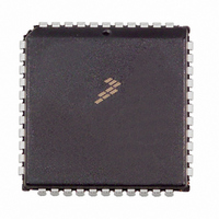
MC68HC705C9ACFN Freescale Semiconductor, MC68HC705C9ACFN Datasheet - Page 71

MC68HC705C9ACFN
Manufacturer Part Number
MC68HC705C9ACFN
Description
IC MCU 2.1MHZ 16K OTP 44-PLCC
Manufacturer
Freescale Semiconductor
Series
HC05r
Datasheet
1.MC705C9ACPE.pdf
(118 pages)
Specifications of MC68HC705C9ACFN
Core Processor
HC05
Core Size
8-Bit
Speed
2.1MHz
Connectivity
SCI, SPI
Peripherals
POR, WDT
Number Of I /o
24
Program Memory Size
16KB (16K x 8)
Program Memory Type
OTP
Ram Size
352 x 8
Voltage - Supply (vcc/vdd)
3 V ~ 5.5 V
Oscillator Type
Internal
Operating Temperature
-40°C ~ 85°C
Package / Case
44-PLCC
Lead Free Status / RoHS Status
Contains lead / RoHS non-compliant
Eeprom Size
-
Data Converters
-
Available stocks
Company
Part Number
Manufacturer
Quantity
Price
Company:
Part Number:
MC68HC705C9ACFN
Manufacturer:
Freescale Semiconductor
Quantity:
10 000
Company:
Part Number:
MC68HC705C9ACFNE
Manufacturer:
RFMD
Quantity:
8 729
Company:
Part Number:
MC68HC705C9ACFNE
Manufacturer:
Freescale Semiconductor
Quantity:
10 000
Chapter 10
Serial Peripheral Interface (SPI)
10.1 Introduction
The serial peripheral interface (SPI) is an interface built into the device which allows several MC68HC05
MCUs, or MC68HC05 MCU plus peripheral devices, to be interconnected within a single printed circuit
board. In an SPI, separate wires are required for data and clock. In the SPI format, the clock is not
included in the data stream and must be furnished as a separate signal. An SPI system may be configured
in one containing one master MCU and several slave MCUs, or in a system in which an MCU is capable
of being a master or a slave.
10.2 Features
Features include:
10.3 SPI Signal Description
The four basic signals (MOSI, MISO, SCK, and SS) are described in the following paragraphs. Each
signal function is described for both the master and slave modes.
Freescale Semiconductor
•
•
•
•
•
•
•
•
•
Full-duplex, four-wire synchronous transfers
Master or slave operation
Bus frequency divided by 2 (maximum) master bit frequency
Bus frequency (maximum) slave bit frequency
Four programmable master bit rates
Programmable clock polarity and phase
End of transmission interrupt flag
Write collision flag protection
Master-master mode fault protection capability
In C9A mode, any SPI output line has to have its corresponding data
direction register bit set. If this bit is clear, the line is disconnected from the
SPI logic and becomes a general-purpose input line. When the SPI is
enabled, any SPI input line is forced to act as an input regardless of what
is in the corresponding data direction register bit.
MC68HC05C9A Advance Information Data Sheet, Rev. 4.1
NOTE
71


