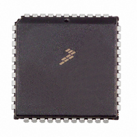
MC68HC705C9ACFN Freescale Semiconductor, MC68HC705C9ACFN Datasheet - Page 76

MC68HC705C9ACFN
Manufacturer Part Number
MC68HC705C9ACFN
Description
IC MCU 2.1MHZ 16K OTP 44-PLCC
Manufacturer
Freescale Semiconductor
Series
HC05r
Datasheet
1.MC705C9ACPE.pdf
(118 pages)
Specifications of MC68HC705C9ACFN
Core Processor
HC05
Core Size
8-Bit
Speed
2.1MHz
Connectivity
SCI, SPI
Peripherals
POR, WDT
Number Of I /o
24
Program Memory Size
16KB (16K x 8)
Program Memory Type
OTP
Ram Size
352 x 8
Voltage - Supply (vcc/vdd)
3 V ~ 5.5 V
Oscillator Type
Internal
Operating Temperature
-40°C ~ 85°C
Package / Case
44-PLCC
Lead Free Status / RoHS Status
Contains lead / RoHS non-compliant
Eeprom Size
-
Data Converters
-
Available stocks
Company
Part Number
Manufacturer
Quantity
Price
Company:
Part Number:
MC68HC705C9ACFN
Manufacturer:
Freescale Semiconductor
Quantity:
10 000
Company:
Part Number:
MC68HC705C9ACFNE
Manufacturer:
RFMD
Quantity:
8 729
Company:
Part Number:
MC68HC705C9ACFNE
Manufacturer:
Freescale Semiconductor
Quantity:
10 000
Serial Peripheral Interface (SPI)
10.5.2 Serial Peripheral Status Register
The SPI status register (SPSR), shown in
SPIF — SPI Transfer Complete Flag
WCOL — Write Collision Bit
MODF — Mode Fault
76
•
•
•
The serial peripheral data transfer flag bit is set upon completion of data transfer between the
processor and external device. If SPIF goes high, and if SPIE is set, a serial peripheral interrupt is
generated. Clearing the SPIF bit is accomplished by reading the SPSR (with SPIF set) followed by an
access of the SPDR. Following the initial transfer, unless SPSR is read (with SPIF set) first, attempts
to write to SPDR are inhibited.
The write collision bit is set when an attempt is made to write to the serial peripheral data register while
data transfer is taking place. If CPHA is 0, a transfer is said to begin when SS goes low and the transfer
ends when SS goes high after eight clock cycles on SCK. When CPHA is 1, a transfer is said to begin
the first time SCK becomes active while SS is low and the transfer ends when the SPIF flag gets set.
Clearing the WCOL bit is accomplished by reading the SPSR (with WCOL set) followed by an access
to SPDR.
The mode fault flag indicates that there may have been a multi-master conflict for system control and
allows a proper exit from system operation to a reset or default system state. The MODF bit is normally
clear, and is set only when the master device has its SS pin pulled low. Setting the MODF bit affects
the internal serial peripheral interface system in the following ways.
SPI transmission complete
Write collision
Mode fault
1.
2.
3.
An SPI interrupt is generated if SPIE = 1.
The SPE bit is cleared. This disables the SPI.
The MSTR bit is cleared, thus forcing the device into the slave mode.
$000B
Reset:
Read:
Write:
SPIF
Bit 7
0
MC68HC05C9A Advance Information Data Sheet, Rev. 4.1
SPR[1:0]
= Unimplemented
WCOL
00
01
10
11
Table 10-1. SPI Clock Rate Selection
6
0
Figure 10-5. SPI Status Register
Figure
5
0
10-5, contains flags to signal the following conditions:
MODF
4
0
Internal Clock ÷ 16
Internal Clock ÷ 32
Internal Clock ÷ 2
Internal Clock ÷ 4
SPI Clock Rate
3
0
2
0
1
0
Freescale Semiconductor
Bit 0
0


