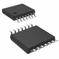
LMP7709MT/NOPB National Semiconductor, LMP7709MT/NOPB Datasheet - Page 17

LMP7709MT/NOPB
Manufacturer Part Number
LMP7709MT/NOPB
Description
IC AMP PREC RRIO QUAD 14-TSSOP
Manufacturer
National Semiconductor
Series
LMP®, PowerWise®r
Datasheet
1.LMP7707MFNOPB.pdf
(26 pages)
Specifications of LMP7709MT/NOPB
Amplifier Type
General Purpose
Number Of Circuits
4
Output Type
Rail-to-Rail
Slew Rate
5.9 V/µs
Gain Bandwidth Product
15MHz
Current - Input Bias
0.2pA
Voltage - Input Offset
37µV
Current - Supply
3.2mA
Current - Output / Channel
86mA
Voltage - Supply, Single/dual (±)
2.7 V ~ 12 V, ±1.35 V ~ 6 V
Operating Temperature
-40°C ~ 125°C
Mounting Type
Surface Mount
Package / Case
14-TSSOP
Lead Free Status / RoHS Status
Lead free / RoHS Compliant
-3db Bandwidth
-
Other names
LMP7709MT
This amplifier is unity gain stable, because the phase shift is
still < 180°, when the gain crosses 0 dB (unity gain).
Stability can be expressed in two different ways:
Phase Margin This is the phase difference between the ac-
Gain Margin
The amplifier is supposed to be used with negative feedback
but a phase shift of 180° will turn the negative feedback into
positive feedback, resulting in oscillations. A phase shift of
180° is not a problem when the gain is smaller than 0 dB, so
the critical point for stability is 180° phase shift at 0 dB gain.
The gain margin and phase margin express the margin en-
hancing overall stability between the amplifiers response and
this critical point.
DECOMPENSATED AMPLIFIERS
Decompensated amplifiers, such as the LMP7707/LMP7708/
LMP7709, are designed to maximize the bandwidth and slew
rate without any additional power consumption over the unity
gain stable op amp. That is, a decompensated op amp has a
higher bandwidth to power ratio than an equivalent compen-
sated op amp. Compared with the unity gain stable amplifier,
the decompensated version has the following advantages:
1.
2.
3.
Figure 7 shows the frequency response of the decompensat-
ed amplifier.
A wider closed loop bandwidth.
Better slew rate due to reduced compensation
capacitance within the op amp.
Better Full Power Bandwidth, given with Equation 2.
FIGURE 6. Open Loop Frequency Response
Compensated Amplifier (LMP7701)
tual phase shift and 180°, at the point where
the gain is 0 dB.
This is the gain difference relative to 0 dB, at
the frequency where the phase shift crosses
the 180°.
202037aa
(2)
17
As shown in Figure 7, the reduced internal compensation
moves the first pole to higher frequencies. The second open
loop pole for the LMP7707/LMP7708/LMP7709 occurs at 4
MHz. The extrapolated unity gain (see dashed line in Figure
7) occurs at 14 MHz. An ideal two pole system would give a
phase margin of > 45° at the location of the second pole. Un-
fortunately, the LMP7707/LMP7708/LMP7709 have parasitic
poles close to the second pole, giving a phase margin closer
to 0°. The LMP7707/LMP7708/LMP7709 can be used at fre-
quencies where the phase margin is > 45°. The frequency
where the phase margin is 45° is at 2.4 MHz. The corre-
sponding value of the open loop gain (also called G
times.
Stability has only to do with the loop gain and not with the
forward gain (G) of the op amp. For high gains, the feedback
network is attenuating and this reduces the loop gain; there-
fore the op amp will be stable for G > G
measures are required. For low gains the feedback network
attenuation may not be sufficient to ensure loop stability for a
decompensated amplifier. However, with an external com-
pensation network decompensated amplifiers can still be
made stable while maintaining their advantages over unity
gain stable amplifiers.
EXTERNAL COMPENSATION FOR GAINS LOWER THAN
G
This section explains how decompensated amplifiers can be
used in configurations requiring a gain lower than G
next sections the concept of the feedback factor is introduced.
Subsequently, an explanation is given how stability can be
determined using the frequency response curve of the op amp
together with the feedback factor. Using the circuit theory, it
will be explained how decompensated amplifiers can be sta-
bilized at lower gains.
FEEDBACK THEORY
Stability issues can be analyzed by verifying the loop gain
function GF, where G is the open loop gain of the amplifier
and F is the feedback factor of the feedback circuit.
The feedback function (F) of arbitrary electronic circuits, as
shown in Figure 8, is defined as the ratio of the input and out-
put signal of the same circuit.
MIN.
FIGURE 7. Open Loop Frequency Response
Decompensated Amplifier (LMP7707)
MIN
and no special
www.national.com
MIN
202037a9
MIN
. In the
) is 6


