LPV531MK/NOPB National Semiconductor, LPV531MK/NOPB Datasheet - Page 16
LPV531MK/NOPB
Manufacturer Part Number
LPV531MK/NOPB
Description
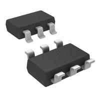
IC OPAMP PROG R-R OUT TSOT23-6
Manufacturer
National Semiconductor
Series
PowerWise®r
Datasheet
1.LPV531MKNOPB.pdf
(17 pages)
Specifications of LPV531MK/NOPB
Amplifier Type
General Purpose
Number Of Circuits
1
Output Type
Rail-to-Rail
Slew Rate
2.5 V/µs
Gain Bandwidth Product
4.6MHz
Current - Input Bias
0.05pA
Voltage - Input Offset
1000µV
Current - Supply
425µA
Current - Output / Channel
24mA
Voltage - Supply, Single/dual (±)
2.7 V ~ 5.5 V
Operating Temperature
-40°C ~ 85°C
Mounting Type
Surface Mount
Package / Case
TSOT-23-6, TSOT-6
Number Of Channels
1
Voltage Gain Db
128 dB
Common Mode Rejection Ratio (min)
72 dB
Input Offset Voltage
4.5 mV at 5 V
Operating Supply Voltage
5 V
Supply Current
0.53 mA at 5 V
Maximum Operating Temperature
+ 85 C
Minimum Operating Temperature
- 40 C
Lead Free Status / RoHS Status
Lead free / RoHS Compliant
-3db Bandwidth
-
Lead Free Status / Rohs Status
Details
Other names
LPV531MK
LPV531MKTR
LPV531MKTR


www.national.com
Typical Application
For simplicity, the op amp is modelled as an ideal integrator
with a unity gain frequency of A
(or gain) in the frequency domain is A
equations in the frequency domain, ignoring C
ment, results in the following equation for the gain:
It can be inferred from the denominator of the transfer func-
tion that it has two poles, whose expressions can be ob-
tained by solving for the roots of the denominator:
Equation (2) shows that as the values of R
increased, the magnitude of the poles is reduced, and hence
the bandwidth of the amplifier is decreased. Furthermore, R
and R
2
are related by the gain of the amplifier.
0
. Hence, its transfer function
(Continued)
0
/s. Solving the circuit
1
F
and R
for the mo-
2
are
(1)
(2)
1
16
A
R
It is the presence of pairs of poles in Equation (2) that causes
gain peaking. In order to eliminate this effect, the poles
should be placed in Butterworth position, since poles in
Butterworth position do not cause gain peaking. To achieve a
Butterworth pair, the quantity under the square root in Equa-
tion 2 should be set to equal −1. Using this fact and the
relation between R
found. This is shown in Equation (3). If R
larger than this optimum value, gain peaking will occur.
In Figure 9, C
and to increase stability. In addition, C
the gain peaking that can be caused by having a larger
feedback resistor.
V
2
= −R
= −A
V
2
/R
R
1
1
, or alternatively
F
is added to compensate for input capacitance
1
and R
2
, the optimum value for R
F
reduce or eliminates
1
is chosen to be
1
can be
(3)
Related parts for LPV531MK/NOPB
Image
Part Number
Description
Manufacturer
Datasheet
Request
R

Part Number:
Description:
IC,Operational Amplifier,SINGLE,BIPOLAR,TSOP,6PIN,PLASTIC
Manufacturer:
National Semiconductor
Part Number:
Description:
National Semiconductor [8-Bit D/A Converter]
Manufacturer:
National Semiconductor
Datasheet:
Part Number:
Description:
National Semiconductor [Media Coprocessor]
Manufacturer:
National Semiconductor
Datasheet:
Part Number:
Description:
Digitally Controlled Tone and Volume Circuit with Stereo Audio Power Amplifier, Microphone Preamp Stage and National 3D Sound
Manufacturer:
National Semiconductor
Datasheet:
Part Number:
Description:
Digitally Controlled Tone and Volume Circuit with Stereo Audio Power Amplifier, Microphone Preamp Stage and National 3D Sound
Manufacturer:
National Semiconductor
Datasheet:
Part Number:
Description:
AC97 Rev 2 Codec with Sample Rate Conversion and National 3D Sound
Manufacturer:
National Semiconductor
Part Number:
Description:
Manufacturer:
National Semiconductor
Datasheet:
Part Number:
Description:
Manufacturer:
National Semiconductor
Datasheet:
Part Number:
Description:
General Purpose, Low Voltage, Low Power, Rail-to-Rail Output Operational Amplifiers
Manufacturer:
National Semiconductor
Datasheet:
Part Number:
Description:
8-bit 20 MSPS flash A/D converter.
Manufacturer:
National Semiconductor
Datasheet:
Part Number:
Description:
Low Noise Quad Operational Amplifier
Manufacturer:
National Semiconductor
Datasheet:
Part Number:
Description:
Quad Differential Line Receivers
Manufacturer:
National Semiconductor
Datasheet:
Part Number:
Description:
Quad High Speed Trapezoidal? Bus Transceiver
Manufacturer:
National Semiconductor
Datasheet:
Part Number:
Description:
Dual Line Receiver
Manufacturer:
National Semiconductor
Datasheet: