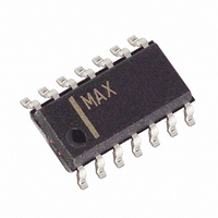
MAX475CSD Maxim Integrated Products, MAX475CSD Datasheet - Page 12

MAX475CSD
Manufacturer Part Number
MAX475CSD
Description
IC OPAMP QUAD 10MHZ 14-SOIC
Manufacturer
Maxim Integrated Products
Datasheet
1.MAX475CPD.pdf
(13 pages)
Specifications of MAX475CSD
Amplifier Type
General Purpose
Number Of Circuits
4
Output Type
Rail-to-Rail
Slew Rate
17 V/µs
Gain Bandwidth Product
12MHz
Current - Input Bias
80nA
Voltage - Input Offset
800µV
Current - Supply
2mA
Voltage - Supply, Single/dual (±)
2.7 V ~ 5.25 V, ±1.35 V ~ 2.625 V
Operating Temperature
-40°C ~ 85°C
Mounting Type
Surface Mount
Package / Case
14-SOIC (3.9mm Width), 14-SOL
Lead Free Status / RoHS Status
Contains lead / RoHS non-compliant
Current - Output / Channel
-
-3db Bandwidth
-
Figure 3. MAX474 Driving 390pF
Figure 4. Capacitive-Load Driving Circuit
The MAX473/MAX474/MAX475’s fast 15V/µs slew rate
maximizes full-power bandwidth (FPBW). The FPBW is
given by:
where the slew rate (SR) is 15V/µs min. Figure 6 shows
the full-power bandwidth as a function of the peak-to-
peak AC output voltage.
V
IN
Driving 390pF in parallel with 10k ,
V
FPBW (Hz) = —————————————
CC
= 5V, buffer configuration
______________________________________________________________________________________
π [V
Full-Power Bandwidth
OUT
peak-to-peak(max)]
10
R L
SR
MAX473/MAX474/
MAX475
C
L
V
OUT
Single/Dual/Quad, 10MHz
Single-Supply Op Amps
Figure 5. The MAX473 easily drives 1000pF using the
Capacitive-Load Driving Circuit (Figure 4).
Figure 6. Full-Power Bandwidth vs. Peak-to-Peak AC Voltage
A good layout improves performance by decreasing
the amount of stray capacitance at the amplifier’s
inputs and output. Since stray capacitance might be
unavoidable, minimize trace lengths and resistor leads,
and place external components as close to the pins as
possible.
100
0.1
10
1
0
OUTPUT VOLTAGE SWING (Vp-p)
FULL-POWER
BANDWIDTH
1
2
GAIN BANDWIDTH
SMALL-SIGNAL
3
4
Layout
11


