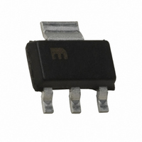
MIC5209-3.3YS Micrel Inc, MIC5209-3.3YS Datasheet - Page 10

MIC5209-3.3YS
Manufacturer Part Number
MIC5209-3.3YS
Description
IC REG LDO 500MA 3.3V SOT-223
Manufacturer
Micrel Inc
Datasheet
1.MIC5209-3.3YS_TR.pdf
(13 pages)
Specifications of MIC5209-3.3YS
Regulator Topology
Positive Fixed
Voltage - Output
3.3V
Voltage - Input
Up to 16V
Voltage - Dropout (typical)
0.35V @ 500mA
Number Of Regulators
1
Current - Output
500mA
Operating Temperature
-40°C ~ 125°C
Mounting Type
Surface Mount
Package / Case
SOT-223 (3 leads + Tab), SC-73, TO-261
Output Voltage Fixed
3.3V
Dropout Voltage Vdo
10mV
No. Of Pins
3
Output Current
500mA
Operating Temperature Range
-40°C To +125°C
Msl
MSL 3 - 168 Hours
Termination Type
SMD
Lead Free Status / RoHS Status
Lead free / RoHS Compliant
Current - Limit (min)
-
Lead Free Status / RoHS Status
Lead free / RoHS Compliant, Lead free / RoHS Compliant
Other names
576-3516-5
MIC5209-3.3YS
MIC5209-3.3YS
Available stocks
Company
Part Number
Manufacturer
Quantity
Price
Company:
Part Number:
MIC5209-3.3YS
Manufacturer:
SST
Quantity:
12 600
Part Number:
MIC5209-3.3YS
Manufacturer:
MICREL/麦瑞
Quantity:
20 000
Part Number:
MIC5209-3.3YS TR
Manufacturer:
MICERL
Quantity:
20 000
Part Number:
MIC5209-3.3YSTR
Manufacturer:
MICREL/麦瑞
Quantity:
20 000
Fixed Regulator Circuits
Figure 1 shows a basic MIC5209-x.xBM (SO-8) fi xed-voltage
regulator circuit. See Figure 5 for a similar confi guration us-
ing the more thermally-effi cient MIC5209-x.xBS (SOT-223).
A 1µF minimum output capacitor is required for basic fi xed-
voltage applications.
Figure 2 includes the optional 470pF noise bypass capacitor
between BYP and GND to reduce output noise. Note that the
minimum value of C
capacitor is used.
Adjustable Regulator Circuits
The MIC5209BM/U can be adjusted to a specifi c output volt-
age by using two external resistors (Figure 3). The resistors
set the output voltage based on the equation:
This equation is correct due to the confi guration of the
bandgap reference. The bandgap voltage is relative to the
output, as seen in the block diagram. Traditional regula-
tors normally have the reference voltage relative to ground;
therefore, their equations are different from the equation for
the MIC5209BM/U.
Although ADJ is a high-impedance input, for best performance,
R2 should not exceed 470kΩ.
M9999-060906
Figure 2. Ultra-Low-Noise Fixed Voltage Regulator
Figure 3. Low-Noise Adjustable Voltage Regulator
Figure 1. Low-Noise Fixed Voltage Regulator
V
V
V
OUT
OUT
V
IN
= 1.242V
V
IN
V
IN
2
1
MIC5209-x.xBM
2
1
I I N N
E E N N
MIC5209BM
OUT
I I N N
E E N N
MIC5209-x.xBM
2
1
I I N N
EN
GND
5–8
1
must be increased when the bypass
GND
5–8
+
GND
OUT
OUT
ADJ
ADJ
OUT
OUT
BYP
BYP
R2
R1
5–8
OUT
OUT
BYP
470pF
3
4
3
4
R1
R2
3
4
1µF
V
2.2µF
OUT
V
1µF
OUT
V
OUT
10
Figure 4 includes the optional 470pF bypass capacitor from
ADJ to GND to reduce output noise.
Slot-1 Power Supply
Intel’s Pentium II processors have a requirement for a 2.5V
±5% power supply for a clock synthesizer and its associated
loads. The current requirement for the 2.5V supply is depen-
dant upon the clock synthesizer used, the number of clock
outputs, and the type of level shifter (from core logic levels to
2.5V levels). Intel estimates a worst-case load of 320mA.
The MIC5209 was designed to provide the 2.5V power
requirement for Slot-1 applications. Its guaranteed perfor-
mance of 2.5V ±3% at 500mA allows adequate margin for
all systems, and its dropout voltage of 500mV means that it
operates from a worst-case 3.3V supply where the voltage
can be as low as 3.0V.
A Slot-1 power supply (Figure 5) is easy to implement. Only
two capacitors are necessary, and their values are not criti-
cal. C
0.1µF. C
response, and compensates the internal regulator control
loop. Its value should be at least 22µF. C
be increased as much as desired.
Slot-1 Power Supply Power Dissipation
Powered from a 3.3V supply, the Slot-1 power supply of
Figure 5 has a nominal effi ciency of 75%. At the maximum
anticipated Slot 1 load (320mA), the nominal power dissipa-
tion is only 256mW.
The SOT-223 package has suffi cient thermal characteristics
for wide design margins when mounted on a single layer
copper-clad printed circuit board. The power dissipation of
the MIC5209 is calculated using the voltage drop across the
device × output current plus supply voltage × ground current.
Figure 4. Ultra-Low-Noise Adjustable Application.
IN
bypasses the internal circuitry and should be at least
OUT
V
IN
0.1µF
Figure 5. Slot-1 Power Supply
provides output fi ltering, improves transient
V
C
2
1
IN
IN
EN
IN
MIC5209BM
GND
MIC5209-x.xBS
1
5–8
I I N N
OUT
ADJ
470pF
GND
3
4
2,TAB
OUT
OUT
3
R1
R2
C
22µF
V
IN
OUT
OUT
and C
2.2µF
V
OUT
June 2006
OUT
may


