MIC5209-3.3YS Micrel Inc, MIC5209-3.3YS Datasheet - Page 9
MIC5209-3.3YS
Manufacturer Part Number
MIC5209-3.3YS
Description
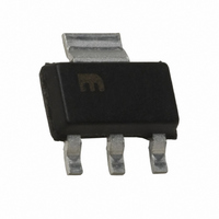
IC REG LDO 500MA 3.3V SOT-223
Manufacturer
Micrel Inc
Datasheet
1.MIC5209-3.3YS_TR.pdf
(13 pages)
Specifications of MIC5209-3.3YS
Regulator Topology
Positive Fixed
Voltage - Output
3.3V
Voltage - Input
Up to 16V
Voltage - Dropout (typical)
0.35V @ 500mA
Number Of Regulators
1
Current - Output
500mA
Operating Temperature
-40°C ~ 125°C
Mounting Type
Surface Mount
Package / Case
SOT-223 (3 leads + Tab), SC-73, TO-261
Output Voltage Fixed
3.3V
Dropout Voltage Vdo
10mV
No. Of Pins
3
Output Current
500mA
Operating Temperature Range
-40°C To +125°C
Msl
MSL 3 - 168 Hours
Termination Type
SMD
Lead Free Status / RoHS Status
Lead free / RoHS Compliant
Current - Limit (min)
-
Lead Free Status / RoHS Status
Lead free / RoHS Compliant, Lead free / RoHS Compliant
Other names
576-3516-5
MIC5209-3.3YS
MIC5209-3.3YS
Available stocks
Company
Part Number
Manufacturer
Quantity
Price
Company:

Part Number:
MIC5209-3.3YS
Manufacturer:
SST
Quantity:
12 600
Part Number:
MIC5209-3.3YS
Manufacturer:
MICREL/麦瑞
Quantity:
20 000
Part Number:
MIC5209-3.3YS TR
Manufacturer:
MICERL
Quantity:
20 000
Part Number:
MIC5209-3.3YSTR
Manufacturer:
MICREL/麦瑞
Quantity:
20 000


Applications Information
Enable/Shutdown
Enable is available only on devices in the SO-8 (M) and
TO-263-5 (U) packages.
Forcing EN (enable/shutdown) high (> 2V) enables the regula-
tor. EN is compatible with CMOS logic. If the enable/shutdown
feature is not required, connect EN to IN (supply input).
Input Capacitor
A 1µF capacitor should be placed from IN to GND if there is
more than 10 inches of wire between the input and the ac
fi lter capacitor or if a battery is used as the input.
Output Capacitor
An output capacitor is required between OUT and GND to
prevent oscillation. The minimum size of the output capacitor
is dependent upon whether a reference bypass capacitor is
used. 1µF minimum is recommended when C
(see Figure 1). 2.2µF minimum is recommended when C
is 470pF (see Figure 2). Larger values improve the regulator’s
transient response.
The output capacitor should have an ESR (equivalent series
resistance) of about 1Ω and a resonant frequency above
1MHz. Ultra-low-ESR capacitors can cause a low amplitude
oscillation on the output and/or underdamped transient re-
sponse. Most tantalum or aluminum electrolytic capacitors
are adequate; fi lm types will work, but are more expensive.
Since many aluminum electrolytics have electrolytes that
freeze at about –30°C, solid tantalums are recommended
for operation below –25°C.
At lower values of output current, less output capacitance
is needed for output stability. The capacitor can be reduced
to 0.47µF for current below 10mA or 0.33µF for currents
below 1mA.
No-Load Stability
The MIC5209 will remain stable and in regulation with no load
(other than the internal voltage divider) unlike many other
voltage regulators. This is especially important in CMOS
RAM keep-alive applications.
Reference Bypass Capacitor
BYP (reference bypass) is available only on devices in SO-8
and TO-263-5 packages.
BYP is connected to the internal voltage reference. A 470pF
capacitor (C
reference, providing a signifi cant reduction in output noise
(ultra-low-noise performance). Because C
phase margin, the output capacitor should be increased to
at least 2.2µF to maintain stability.
The start-up speed of the MIC5209 is inversely proportional
to the size of the reference bypass capacitor. Applications
requiring a slow ramp-up of output voltage should consider
larger values of C
consider omitting C
If output noise is not critical, omit C
open.
June 2006
BYP
) connected from BYP to GND quiets this
BYP
BYP
. Likewise, if rapid turn-on is necessary,
.
BYP
BYP
and leave BYP
BYP
reduces the
is not used
BYP
9
Thermal Considerations
The SOT-223 has a ground tab which allows it to dissipate
more power than the SO-8. Refer to “Slot-1 Power Supply”
for details. At 25°C ambient, it will operate reliably at 2W
dissipation with “worst-case” mounting (no ground plane,
minimum trace widths, and FR4 printed circuit board).
Thermal resistance values for the SO-8 represent typical
mounting on a 1”-square, copper-clad, FR4 circuit board.
For greater power dissipation, SO-8 versions of the MIC5209
feature a fused internal lead frame and die bonding arrange-
ment that reduces thermal resistance when compared to
standard SO-8 packages.
Multilayer boards with a ground plane, wide traces near the
pads, and large supply-bus lines will have better thermal con-
ductivity and will also allow additional power dissipation.
For additional heat sink characteristics, please refer to Mi-
crel Application Hint 17, “Designing P.C. Board Heat Sinks”,
included in Micrel’s Databook. For a full discussion of heat
sinking and thermal effects on voltage regulators, refer to
Regulator Thermals section of Micrel’s Designing with Low-
Dropout Voltage Regulators handbook.
Low-Voltage Operation
The MIC5209-1.8 and MIC5209-2.5 require special con-
sideration when used in voltage-sensitive systems. They
may momentarily overshoot their nominal output voltages
unless appropriate output and bypass capacitor values are
chosen.
During regulator power up, the pass transistor is fully satu-
rated for a short time, while the error amplifi er and voltage
reference are being powered up more slowly from the output
(see “Block Diagram”). Selecting larger output and bypass
capacitors allows additional time for the error amplifi er and
reference to turn on and prevent overshoot.
To ensure that no overshoot is present when starting up into
a light load (100µA), use a 4.7µF output capacitance and
470pF bypass capacitance. This slows the turn-on enough
to allow the regulator to react and keep the output voltage
from exceeding its nominal value. At heavier loads, use a
10µF output capacitance and 470pF bypass capacitance.
Lower values of output and bypass capacitance can be used,
depending on the sensitivity of the system.
Applications that can withstand some overshoot on the output
of the regulator can reduce the output capacitor and/or reduce
or eliminate the bypass capacitor. Applications that are not
sensitive to overshoot due to power-on reset delays can use
normal output and bypass capacitor confi gurations.
Please note the junction temperature range of the regulator
at 1.8V output (fi xed and adjustable) is 0˚C to +125˚C.
Package
Package
SOT-223 (S)
SOT-223 (S)
SO-8 (M)
SO-8 (M)
SO-8 (M)
TO-263-5 (U)
TO-263-5 (U)
3x3 MLF (ML)
3x3 MLF (ML)
3x3 MLF (ML)
Table 1. MIC5209 Thermal Resistance
50°C/W
50°C/W
50°C/W
50°C/W
50°C/W
63°C/W
63°C/W
63°C/W
θ
—
—
JA
20°C/W
20°C/W
20°C/W
8°C/W
8°C/W
2°C/W
2°C/W
2°C/W
2°C/W
2°C/W
θ
JC
M9999-060906
Related parts for MIC5209-3.3YS
Image
Part Number
Description
Manufacturer
Datasheet
Request
R

Part Number:
Description:
IC REG LDO 500MA 1% 3.6V 8-SOIC
Manufacturer:
Micrel Inc
Datasheet:
Part Number:
Description:
IC REG LDO 500MA 1% 3.0V 8-SOIC
Manufacturer:
Micrel Inc
Datasheet:

Part Number:
Description:
IC REG LDO 500MA 2.5V SOT-223
Manufacturer:
Micrel Inc
Datasheet:
Part Number:
Description:
IC REG LDO 500MA 3.3V LN 8SOIC
Manufacturer:
Micrel Inc
Datasheet:
Part Number:
Description:
IC REG LDO 500MA 1% 2.5V 8-SOIC
Manufacturer:
Micrel Inc
Datasheet:
Part Number:
Description:
IC REG LDO 500MA 1.8V LN 8SOIC
Manufacturer:
Micrel Inc
Datasheet:
Part Number:
Description:
IC REG LDO 500MA 2.5V LN SOT223
Manufacturer:
Micrel Inc
Datasheet:
Part Number:
Description:
IC REG LDO 500MA 3.3V LN 8SOIC
Manufacturer:
Micrel Inc
Datasheet:
Part Number:
Description:
IC REG LDO 500MA 3.3V LN SOT223
Manufacturer:
Micrel Inc
Datasheet:
Part Number:
Description:
IC REG LDO 500MA 5.0V LN SOT223
Manufacturer:
Micrel Inc
Datasheet:

Part Number:
Description:
IC REG LDO 500MA 5.0V LN TO263-5
Manufacturer:
Micrel Inc
Datasheet:
Part Number:
Description:
IC REG LDO 500MA 1% 1.8V TO263-5
Manufacturer:
Micrel Inc
Datasheet:
Part Number:
Description:
IC REG LDO 500MA 1% 2.5V 8-SOIC
Manufacturer:
Micrel Inc
Datasheet:
Part Number:
Description:
IC REG LDO 500MA 1% 2.5V TO263-5
Manufacturer:
Micrel Inc
Datasheet:
Part Number:
Description:
IC REG LDO 500MA 1% 3.0V 8-SOIC
Manufacturer:
Micrel Inc
Datasheet: