MAX1819EBL33+T Maxim Integrated Products, MAX1819EBL33+T Datasheet - Page 7
MAX1819EBL33+T
Manufacturer Part Number
MAX1819EBL33+T
Description
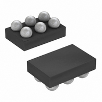
IC REG LDO 3.3V/ADJ 500MA 6-UCSP
Manufacturer
Maxim Integrated Products
Datasheet
1.MAX1819EBL33T.pdf
(9 pages)
Specifications of MAX1819EBL33+T
Regulator Topology
Positive Fixed or Adjustable
Voltage - Output
3.3V, 1.25 ~ 5 V
Voltage - Input
2.5 ~ 5.5 V
Voltage - Dropout (typical)
0.133V @ 500mA, -
Number Of Regulators
1
Current - Output
500mA (Min)
Operating Temperature
-40°C ~ 85°C
Mounting Type
Surface Mount
Package / Case
6-UCSP®
Number Of Outputs
1
Polarity
Positive
Input Voltage Max
5.5 V
Output Voltage
1.25 V to 5 V, 3.3 V
Output Type
Adjustable, Fixed
Dropout Voltage (max)
0.232 V at 500 mA
Output Current
500 mA
Line Regulation
0 %
Load Regulation
0.4 %
Voltage Regulation Accuracy
1 %
Maximum Power Dissipation
0.84 W
Maximum Operating Temperature
+ 85 C
Mounting Style
SMD/SMT
Minimum Operating Temperature
- 40 C
Reference Voltage
1.25 V
Lead Free Status / RoHS Status
Lead free / RoHS Compliant
Current - Limit (min)
-
Lead Free Status / Rohs Status
Lead free / RoHS Compliant


The power-OK (POK) output pulls low when OUT is less
than 93% of the nominal regulation voltage. Once OUT
exceeds 93% of the nominal voltage, POK goes high
impedance. POK is an open-drain N-channel output. To
obtain a voltage signal, connect a pullup resistor from
POK to OUT. A 100kΩ resistor works well for most appli-
cations. POK can be used as a power-OK signal to a
microcontroller (µC), or drive an external LED to indicate
power failure. When the MAX1819 is shut down, POK is
held low independent of the output voltage. If unused,
leave POK grounded or unconnected.
The MAX1819 monitors and controls the pass transis-
tor’s gate voltage, limiting the output current to 1.0A
(typ). This current limit doubles when the output voltage
is within 4% of the nominal value to improve perfor-
mance with large load transients.
Thermal overload protection limits total power dissipa-
tion in the MAX1819. When the junction temperature
exceeds T
pass transistor, allowing the IC to cool. The thermal
sensor turns the pass transistor on again after the junc-
tion temperature cools by 20°C, resulting in a pulsed
output during continuous thermal overload conditions.
Thermal overload protection protects the MAX1819 in
the event of fault conditions. For continuous operation,
do not exceed the absolute maximum junction-temper-
ature rating of T
Figure 2. Adjustable Output Using External Feedback
Resistors
V
IN
500mA Low-Dropout Linear Regulator in UCSP
= 2.5V TO 5.5V
ON
OFF
1µF
C
J
IN
= +170°C, a thermal sensor turns off the
J
= +150°C.
Thermal Overload Protection
_______________________________________________________________________________________
IN
SHDN
POK
MAX1819
GND
OUT
SET
Current Limit
C
3.3µF
OUT
POK Output
R1 = R2
V
1.25V
R
R
OUT
2
1
V
- 1
OUT
The MAX1819’s maximum power dissipation depends
on the thermal resistance of the IC package and circuit
board, the temperature difference between the die
junction and ambient air, and the rate of air flow. The
power dissipated in the device is P = I
V
840mW at T
where T
the MAX1819 die junction and the surrounding air, θ
is the thermal resistance of the junction to the base,
and θ
board, copper traces, and other materials to the sur-
rounding air. For best heatsinking, the copper area
should be equally shared between the IN, OUT, and
GND pins.
The MAX1819 delivers up to 0.5A RMS and operates
with input voltages up to 5.5V, but not simultaneously.
High output currents can only be sustained when input-
output differential voltages are low, as shown in Figure 3.
Figure 3. Power Operating Regions—Maximum Output vs.
Supply Voltage
OUT
Operating Region and Power Dissipation
). The maximum allowed power dissipation is
BA
J
P
is the thermal resistance through the PC
- T
600
400
200
MAX
A
0
A
2.5
= +70°C or:
MAXIMUM RECOMMENDED
OUTPUT CURRENT
is the temperature difference between
V
= (T
OUT
MAXIMUM OUTPUT CURRENT
3.0
(POWER DISSIPATION LIMIT)
= 1.8V
J(MAX)
V
vs. INPUT VOLTAGE
OUT
3.5
INPUT VOLTAGE (V)
= 2.5V
4.0
- T
V
OUT
A
4.5
) / ( θ
= 3.3V
5.0
T
T
JB
A
A
= +70°C
= +85°C
5.5
+ θ
6.0
BA
OUT
)
× (V
IN
JB
7
-
Related parts for MAX1819EBL33+T
Image
Part Number
Description
Manufacturer
Datasheet
Request
R

Part Number:
Description:
MAX7528KCWPMaxim Integrated Products [CMOS Dual 8-Bit Buffered Multiplying DACs]
Manufacturer:
Maxim Integrated Products
Datasheet:
Part Number:
Description:
Single +5V, fully integrated, 1.25Gbps laser diode driver.
Manufacturer:
Maxim Integrated Products
Datasheet:
Part Number:
Description:
Single +5V, fully integrated, 155Mbps laser diode driver.
Manufacturer:
Maxim Integrated Products
Datasheet:
Part Number:
Description:
VRD11/VRD10, K8 Rev F 2/3/4-Phase PWM Controllers with Integrated Dual MOSFET Drivers
Manufacturer:
Maxim Integrated Products
Datasheet:
Part Number:
Description:
Highly Integrated Level 2 SMBus Battery Chargers
Manufacturer:
Maxim Integrated Products
Datasheet:
Part Number:
Description:
Current Monitor and Accumulator with Integrated Sense Resistor; ; Temperature Range: -40°C to +85°C
Manufacturer:
Maxim Integrated Products
Part Number:
Description:
TSSOP 14/A�/RS-485 Transceivers with Integrated 100O/120O Termination Resis
Manufacturer:
Maxim Integrated Products
Part Number:
Description:
TSSOP 14/A�/RS-485 Transceivers with Integrated 100O/120O Termination Resis
Manufacturer:
Maxim Integrated Products
Part Number:
Description:
QFN 16/A�/AC-DC and DC-DC Peak-Current-Mode Converters with Integrated Step
Manufacturer:
Maxim Integrated Products
Part Number:
Description:
TDFN/A/65V, 1A, 600KHZ, SYNCHRONOUS STEP-DOWN REGULATOR WITH INTEGRATED SWI
Manufacturer:
Maxim Integrated Products
Part Number:
Description:
Integrated Temperature Controller f
Manufacturer:
Maxim Integrated Products
Part Number:
Description:
SOT23-6/I�/45MHz to 650MHz, Integrated IF VCOs with Differential Output
Manufacturer:
Maxim Integrated Products
Part Number:
Description:
SOT23-6/I�/45MHz to 650MHz, Integrated IF VCOs with Differential Output
Manufacturer:
Maxim Integrated Products
Part Number:
Description:
EVALUATION KIT/2.4GHZ TO 2.5GHZ 802.11G/B RF TRANSCEIVER WITH INTEGRATED PA
Manufacturer:
Maxim Integrated Products
Part Number:
Description:
QFN/E/DUAL PCIE/SATA HIGH SPEED SWITCH WITH INTEGRATED BIAS RESISTOR
Manufacturer:
Maxim Integrated Products
Datasheet: