MAX1819EBL33+T Maxim Integrated Products, MAX1819EBL33+T Datasheet - Page 8
MAX1819EBL33+T
Manufacturer Part Number
MAX1819EBL33+T
Description
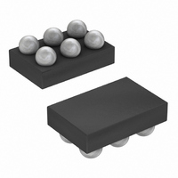
IC REG LDO 3.3V/ADJ 500MA 6-UCSP
Manufacturer
Maxim Integrated Products
Datasheet
1.MAX1819EBL33T.pdf
(9 pages)
Specifications of MAX1819EBL33+T
Regulator Topology
Positive Fixed or Adjustable
Voltage - Output
3.3V, 1.25 ~ 5 V
Voltage - Input
2.5 ~ 5.5 V
Voltage - Dropout (typical)
0.133V @ 500mA, -
Number Of Regulators
1
Current - Output
500mA (Min)
Operating Temperature
-40°C ~ 85°C
Mounting Type
Surface Mount
Package / Case
6-UCSP®
Number Of Outputs
1
Polarity
Positive
Input Voltage Max
5.5 V
Output Voltage
1.25 V to 5 V, 3.3 V
Output Type
Adjustable, Fixed
Dropout Voltage (max)
0.232 V at 500 mA
Output Current
500 mA
Line Regulation
0 %
Load Regulation
0.4 %
Voltage Regulation Accuracy
1 %
Maximum Power Dissipation
0.84 W
Maximum Operating Temperature
+ 85 C
Mounting Style
SMD/SMT
Minimum Operating Temperature
- 40 C
Reference Voltage
1.25 V
Lead Free Status / RoHS Status
Lead free / RoHS Compliant
Current - Limit (min)
-
Lead Free Status / Rohs Status
Lead free / RoHS Compliant


Capacitors are required at the MAX1819’s input and
output for stable operation over the full temperature
range and with load currents up to 500mA. Connect a
1µF capacitor between IN and ground and a 3.3µF low-
ESR capacitor between OUT and ground. For output
voltages less than 2V, use a 4.7µF low-ESR output
capacitor. The input capacitor (C
impedance of the input supply. Reduce noise and
improve load-transient response, stability, and power-
supply rejection by using larger output capacitors, such
as 10µF.
The output capacitor’s (C
tance (ESR) affects stability and output noise. Use out-
put capacitors with an ESR of 0.1Ω or less to ensure
stability and optimum transient response. Surface-
mount ceramic capacitors have very low ESR and are
commonly available in values up to 10µF. C
C
The MAX1819 is designed to operate with low dropout
voltages and low quiescent currents in battery-powered
systems while still maintaining good noise, transient
response, and AC rejection. See the Typical Operating
Characteristics for a plot of Power-Supply Rejection
Ratio (PSRR) vs. Frequency. When operating from noisy
sources, improved supply-noise rejection and transient
response can be achieved by increasing the values of
the input and output bypass capacitors and through
passive filtering techniques.
500mA Low-Dropout Linear Regulator in UCSP
8
OUT
_______________________________________________________________________________________
use short traces to connect to the MAX1819.
Noise, PSRR, and Transient Response
Applications Information
Capacitor Selection and
OUT
) equivalent series resis-
Regulator Stability
IN
) lowers the source
IN
and
The MAX1819 load-transient response (see the Typical
Operating Characteristics) shows two components of
the output response: a DC shift from the output imped-
ance due to the load current change, and the transient
response. Increasing the output capacitor’s value and
decreasing the ESR attenuates the overshoot.
A regulator’s minimum input-to-output voltage differential
(dropout voltage) determines the lowest usable supply
voltage. In battery-powered systems, this determines the
useful end-of-life battery voltage. Because the MAX1819
uses a P-channel MOSFET pass transistor, its dropout
voltage is a function of drain-to-source on-resistance
(R
Operating Characteristics).
The MAX1819 ground current remains at approximately
150µA in dropout.
TRANSISTOR COUNT: 845
DS(ON)
V
DROPOUT
) multiplied by the load current (see the Typical
Input-Output (Dropout) Voltage
= V
IN
- V
OUT
Chip Information
= R
DS(ON)
× I
OUT
Related parts for MAX1819EBL33+T
Image
Part Number
Description
Manufacturer
Datasheet
Request
R

Part Number:
Description:
MAX7528KCWPMaxim Integrated Products [CMOS Dual 8-Bit Buffered Multiplying DACs]
Manufacturer:
Maxim Integrated Products
Datasheet:
Part Number:
Description:
Single +5V, fully integrated, 1.25Gbps laser diode driver.
Manufacturer:
Maxim Integrated Products
Datasheet:
Part Number:
Description:
Single +5V, fully integrated, 155Mbps laser diode driver.
Manufacturer:
Maxim Integrated Products
Datasheet:
Part Number:
Description:
VRD11/VRD10, K8 Rev F 2/3/4-Phase PWM Controllers with Integrated Dual MOSFET Drivers
Manufacturer:
Maxim Integrated Products
Datasheet:
Part Number:
Description:
Highly Integrated Level 2 SMBus Battery Chargers
Manufacturer:
Maxim Integrated Products
Datasheet:
Part Number:
Description:
Current Monitor and Accumulator with Integrated Sense Resistor; ; Temperature Range: -40°C to +85°C
Manufacturer:
Maxim Integrated Products
Part Number:
Description:
TSSOP 14/A�/RS-485 Transceivers with Integrated 100O/120O Termination Resis
Manufacturer:
Maxim Integrated Products
Part Number:
Description:
TSSOP 14/A�/RS-485 Transceivers with Integrated 100O/120O Termination Resis
Manufacturer:
Maxim Integrated Products
Part Number:
Description:
QFN 16/A�/AC-DC and DC-DC Peak-Current-Mode Converters with Integrated Step
Manufacturer:
Maxim Integrated Products
Part Number:
Description:
TDFN/A/65V, 1A, 600KHZ, SYNCHRONOUS STEP-DOWN REGULATOR WITH INTEGRATED SWI
Manufacturer:
Maxim Integrated Products
Part Number:
Description:
Integrated Temperature Controller f
Manufacturer:
Maxim Integrated Products
Part Number:
Description:
SOT23-6/I�/45MHz to 650MHz, Integrated IF VCOs with Differential Output
Manufacturer:
Maxim Integrated Products
Part Number:
Description:
SOT23-6/I�/45MHz to 650MHz, Integrated IF VCOs with Differential Output
Manufacturer:
Maxim Integrated Products
Part Number:
Description:
EVALUATION KIT/2.4GHZ TO 2.5GHZ 802.11G/B RF TRANSCEIVER WITH INTEGRATED PA
Manufacturer:
Maxim Integrated Products
Part Number:
Description:
QFN/E/DUAL PCIE/SATA HIGH SPEED SWITCH WITH INTEGRATED BIAS RESISTOR
Manufacturer:
Maxim Integrated Products
Datasheet: