RR0816P-164-D Susumu, RR0816P-164-D Datasheet - Page 5
RR0816P-164-D
Manufacturer Part Number
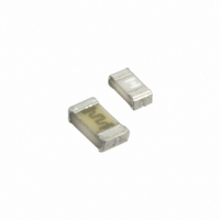
RR0816P-164-D
Description
RES 160K OHM 1/16W .5% 0603 SMD
Manufacturer
Susumu
Series
RRr
Datasheet
1.RR0816P-102-D.pdf
(16 pages)
Specifications of RR0816P-164-D
Resistance (ohms)
160K
Power (watts)
0.063W, 1/16W
Composition
Thin Film
Temperature Coefficient
±25ppm/°C
Tolerance
±0.5%
Size / Dimension
0.063" L x 0.031" W (1.60mm x 0.80mm)
Height
0.016" (0.40mm)
Lead Style
Surface Mount (SMD - SMT)
Package / Case
0603 (1608 Metric)
Resistance In Ohms
160K
Case
0603 (1608 metric)
Resistance
160 KOhms
Power Rating
0.0625 Watt (1/16 Watt)
Voltage Rating
75 Volts
Operating Temperature Range
- 55 C to + 125 C
Termination Style
SMD/SMT
Dimensions
0.8 mm W x 1.6 mm L x 0.4 mm H
Product
Thin Film Resistors SMD
Lead Free Status / RoHS Status
Lead free / RoHS Compliant
Features
-
Lead Free Status / Rohs Status
Details
Other names
RR0816P164D
RR08P160KDTR
RR08P160KDTR


TITLE:
6.1 Electrical
6.1.1 Resistance and tolerance
6.1.2 Temperature characteristic of resistance
6.1.3 Overload
6.1.4 Insulation resistance
Method;
Specification:
Method;
Specification:
Method;
Specification:
Method;
Specification;
Refer to IEC 60115-1, Sub-clause 4.5.
A d.c. or a.c. r.m.s. voltage of 2.5 times the rated voltage shall be applied for 5 sec, and a check shall be
made to see if arcing or other damage happened. Then the resistor shall be maintained without electrical
load for 30 min after which the resistance shall be measured. However the applied voltage shall not
exceed the maximum overload voltage.
For other procedures, refer to IEC 60115-1, Sub-clause 4.13.
Without damage by flash over (spark, arcing), burning or breakdown etc.
Not exceed the specified tolerance on rated resistance in para.4.1.(2).
Resistance shall be measured under standard atmospheric conditions.
When the temperature reaches and is maintained at 100 deg C higher than the temperature of standard
atmospheric conditions, resistance shall be measured again. The measurement shall be made after a
period of 30 min, after each specified temperature is reached.
Not exceed the specified temperature coefficient of resistance in para.4.1.(3).
Change in resistance : ±(0.5%+0.05Ω)
Place the specimen on the groove of metal
plate so that the edge of metal block
positions almost center of both electrodes,
with the surface of insulation enclosure
located
pressurize the block by a force of 1.0±0.2
N.
The test voltage shall be 100±15Vd.c.,
and maintain this voltage for about 1 min.
The insulation resistance shall then be
measured while applying the voltage.
For other procedures, refer to IEC 60115-1,
Sub-clause 4.6.
(1)Between electrodes and insulating enclosure.
(2)Between electrodes and base material.
Chip resistor RR0816 series
downward
Specification for
or
upward
and
Measurement point A on metallic block
SUSUMU
CO.,LTD
Base material
R 0.5
㎜
1000MΩ or more
100MΩ or more
SPEC.NO:
Insulating enclosure surface
RR00-1098
Specimen
Insulating plate
M easurement point B
Presurization by
on m etallic plate
Rev. No.
0
5/16
spring
Related parts for RR0816P-164-D
Image
Part Number
Description
Manufacturer
Datasheet
Request
R

Part Number:
Description:
RES 44.2K OHM 1/16W .5% 0603 SMD
Manufacturer:
Susumu
Datasheet:
Part Number:
Description:
RES 10.0K OHM 1/16W .5% 0603 SMD
Manufacturer:
Susumu
Datasheet:
Part Number:
Description:
RES 56.2K OHM 1/16W .5% 0603 SMD
Manufacturer:
Susumu
Datasheet:
Part Number:
Description:
RES 365 OHM 1/16W .5% 0603 SMD
Manufacturer:
Susumu
Datasheet:
Part Number:
Description:
RES 20.5K OHM 1/16W .5% 0603 SMD
Manufacturer:
Susumu
Datasheet:
Part Number:
Description:
RES 4.64K OHM 1/16W .5% 0603 SMD
Manufacturer:
Susumu
Datasheet:
Part Number:
Description:
RES 18.2K OHM 1/16W .5% 0603 SMD
Manufacturer:
Susumu
Datasheet:
Part Number:
Description:
RES 4.99K OHM 1/16W .5% 0603 SMD
Manufacturer:
Susumu
Datasheet:
Part Number:
Description:
RES 49.9K OHM 1/16W .5% 0603 SMD
Manufacturer:
Susumu
Datasheet:
Part Number:
Description:
RES 6.49K OHM 1/16W .5% 0603 SMD
Manufacturer:
Susumu
Datasheet:
