M52277EVB Freescale Semiconductor, M52277EVB Datasheet - Page 5
M52277EVB
Manufacturer Part Number
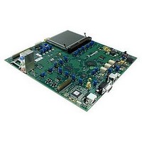
M52277EVB
Description
BOARD DEMO FOR MCF5227
Manufacturer
Freescale Semiconductor
Series
ColdFire®r
Type
MCUr
Specifications of M52277EVB
Contents
Board
Silicon Manufacturer
Freescale
Core Architecture
Coldfire
Core Sub-architecture
Coldfire V2
Silicon Core Number
MCF52
Silicon Family Name
MCF5227x
Peak Reflow Compatible (260 C)
Yes
Rohs Compliant
Yes
For Use With/related Products
MCF52277
Lead Free Status / RoHS Status
Lead free / RoHS Compliant


clock signals and configurations are described below. Please refer to the MCF52277 Reference Manual for
further information on the clocking requirements for the MCF52277.
5.4
The M52277EVB includes a serial boot flash and a program flash memory.
5.4.1
The program flash memory resides on the first block of FlexBus memory. The 128Mbit Spansion flash can
be used for RTOS development. Your software must configure the memory access parameters consistent
with the hardware configuration.
Jumper J8 controls the boot mode of the flash. The default position is 1-2 which selects bottom boot mode.
Setting the jumper to position 2-3, selects top boot mode. This flash device is connected to CS0 and is the
device from which the MCF52277 executes following reset.
5.4.2
The serial boot flash stores configuration parameters and boot code. All of this is loaded into on-chip
SRAM during the processor reset sequence (i.e. when the BOOTMOD signals = 11). The serial boot flash
has a dedicated interface to the MCF52277 processor. When the BOOTMOD = 11, the serial boot facility
sets the configurable power-up options for the processor. As an additional option it can also load code into
the processor memory space at that time.
Through interaction with the MCF52277 processor's reset controller, the serial boot facility accomplishes
all of this before the MCF52277 processor reset negates, ensuring the chip is properly configured when
exiting the reset state.
5.5
The M52277EVB provides 64 Mbytes of on-board Mobile SDRAM (16bit x 32M Micron Mobile
SDRAM). On-board terminations are provided.
Freescale Semiconductor
16MHz Input Oscillator
16MHz Input Crystal
External Clock Input
Boot and Program Flash Memory
SDRAM Interface
Clock
Program Flash
Serial Boot Flash
If the clock selection is changed, the SW3 and SW4 switch settings need to
be changed to reflect the appropriate clock input.
Jumpers J21 and J22 are used to select between clock options. Setting J21
to 2-3 and J22 to 1-2 selects the 16MHz Oscillator option.
Setting J22 to 2-3 selects the 16MHz Crystal option (In this mode, the
setting of J21 is a don’t care).
Setting J21 to1-2 and J22 to 1-2 selects the External Clock Input option.
The external clock can be input on the SMA connector J24.
Table 2. M52277EVB Clock Definitions
M52277 Evaluation Board, Rev. 0.8
NOTE
Description
Frequency
Variable
16MHz
16MHz
5
Related parts for M52277EVB
Image
Part Number
Description
Manufacturer
Datasheet
Request
R

Part Number:
Description:
Manufacturer:
Freescale Semiconductor, Inc
Datasheet:
Part Number:
Description:
Manufacturer:
Freescale Semiconductor, Inc
Datasheet:
Part Number:
Description:
Manufacturer:
Freescale Semiconductor, Inc
Datasheet:
Part Number:
Description:
Manufacturer:
Freescale Semiconductor, Inc
Datasheet:
Part Number:
Description:
Manufacturer:
Freescale Semiconductor, Inc
Datasheet:
Part Number:
Description:
Manufacturer:
Freescale Semiconductor, Inc
Datasheet:
Part Number:
Description:
Manufacturer:
Freescale Semiconductor, Inc
Datasheet:
Part Number:
Description:
Manufacturer:
Freescale Semiconductor, Inc
Datasheet:
Part Number:
Description:
Manufacturer:
Freescale Semiconductor, Inc
Datasheet:
Part Number:
Description:
Manufacturer:
Freescale Semiconductor, Inc
Datasheet:
Part Number:
Description:
Manufacturer:
Freescale Semiconductor, Inc
Datasheet:
Part Number:
Description:
Manufacturer:
Freescale Semiconductor, Inc
Datasheet:
Part Number:
Description:
Manufacturer:
Freescale Semiconductor, Inc
Datasheet:
Part Number:
Description:
Manufacturer:
Freescale Semiconductor, Inc
Datasheet:
Part Number:
Description:
Manufacturer:
Freescale Semiconductor, Inc
Datasheet: