MSA-0436-BLKG Avago Technologies US Inc., MSA-0436-BLKG Datasheet - Page 2
MSA-0436-BLKG
Manufacturer Part Number
MSA-0436-BLKG
Description
AMP MMIC SI BIPOLAR 36MICRO-X
Manufacturer
Avago Technologies US Inc.
Series
-r
Type
General Purposer
Datasheet
1.MSA-0436-TR1G.pdf
(4 pages)
Specifications of MSA-0436-BLKG
Gain
7.5dB ~ 9.5dB
Rf Type
ISM
Current - Supply
50mA
Frequency
0Hz ~ 3.8GHz
Noise Figure
6.5dB
P1db
12.5dBm
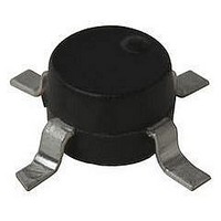
Package / Case
4-SMD (36 micro-X)
Test Frequency
1GHz
Voltage - Supply
4.75V ~ 5.75V
Frequency Range
DC To 3.8GHz
Noise Figure Typ
6.5dB
Power Dissipation Pd
650mW
Supply Current
70mA
Supply Voltage Range
4.75V To 5.75V
Number Of Channels
1
Frequency (max)
25GHz
Output Power
12.5@1000MHzdBm
Power Supply Requirement
Single
Single Supply Voltage (min)
4.75V
Single Supply Voltage (typ)
5.25V
Single Supply Voltage (max)
5.75V
Package Type
Case 36 micro-X
Dual Supply Voltage (min)
Not RequiredV
Dual Supply Voltage (typ)
Not RequiredV
Dual Supply Voltage (max)
Not RequiredV
Pin Count
4
Mounting
Surface Mount
Lead Free Status / RoHS Status
Lead free / RoHS Compliant
Lead Free Status / RoHS Status
Lead free / RoHS Compliant, Lead free / RoHS Compliant
Available stocks
Company
Part Number
Manufacturer
Quantity
Price
Company:

Part Number:
MSA-0436-BLKG
Manufacturer:
AVAGO
Quantity:
600
Part Number:
MSA-0436-BLKG
Manufacturer:
AVAGO/安华高
Quantity:
20 000


MSA-0436 Absolute Maximum Ratings
Notes:
1. Permanent damage may occur if any of these limits are exceeded.
2. T
3. Derate at 7.1 mW/°C for T
4. Storage above +150°C may tarnish the leads of this package making it
5. The small spot size of this technique results in a higher, though more
Electrical Specifications
Note:
1. The recommended operating current range for this device is 30 to 70 mA. Typical performance as a function of current
Ordering Information
Parameter
Device Current
Power Dissipation
RF Input Power
Junction Temperature
Storage Temperature
Symbol
VSWR
G
∆G
f
NF
P
IP
t
V
dV/dT
3 dB
D
Part Numbers
MSA-0436-BLKG
MSA-0436-TR1G
1 dB
d
difficult to solder into a circuit.
accurate determination of q
is on the following page.
P
3
CASE
P
= 25°C.
Power Gain (|S
Gain Flatness
3 dB Bandwidth
Input VSWR
Output VSWR
50 Ω Noise Figure
Output Power at 1 dB Gain Compression
Third Order Intercept Point
Group Delay
Device Voltage
Device Voltage Temperature Coefficient
Parameters and Test Conditions: I
[2,3]
[4]
No. of Devices
21
C
|
[1]
2
> 109°C.
jc
)
, T
than do alternate methods.
1000
100
A
= 25°C
Absolute Maximum
Comments
7" Reel
Bulk
–65 to 150°C
+13 dBm
650 mW
100 mA
150°C
d
= 50 mA, Z
f = 0.1 GHz
f = 0.1 to 2.5 GHz
f = 0.1 to 2.5 GHz
f = 0.1 to 2.5 GHz
f = 1.0 GHz
f = 1.0 GHz
f = 1.0 GHz
f = 1.0 GHz
[1]
O
= 50 Ω
2
Thermal Resistance
Units
mV/°C
dBm
dBm
psec
GHz
dB
dB
dB
V
θ
jc
Min.
= 140°C/W
4.75
7.5
Typ. Max.
1.4:1
1.9:1
±0.6
5.25
12.5
25.5
–8.0
125
8.5
3.8
6.5
[2,5]
±1.0
5.75
9.5
:
Related parts for MSA-0436-BLKG
Image
Part Number
Description
Manufacturer
Datasheet
Request
R

Part Number:
Description:
AMP MMIC SI BIPOLAR 36MICRO-X
Manufacturer:
Avago Technologies US Inc.
Datasheet:

Part Number:
Description:
IC,Microwave/Millimeter Wave Amplifier,SINGLE,BIPOLAR,BEAM LEAD,4PIN,CERAMIC
Manufacturer:
Avago Technologies US Inc.
Datasheet:
Part Number:
Description:
IC,Microwave/Millimeter Wave Amplifier,SINGLE,BIPOLAR,BEAM LEAD,4PIN,CERAMIC
Manufacturer:
Avago Technologies US Inc.
Datasheet:

Part Number:
Description:
AMP MMIC SI BIPOLAR SOT-143
Manufacturer:
Avago Technologies US Inc.
Datasheet:
Part Number:
Description:
IC RF AMP MMIC BIPO SOT-143
Manufacturer:
Avago Technologies US Inc.
Datasheet:

Part Number:
Description:
AMP MMIC SI BIPOLAR 86-SMD PLAST
Manufacturer:
Avago Technologies US Inc.
Datasheet:
Part Number:
Description:
AMP MMIC SI BIPOLAR 86-SMD PLAST
Manufacturer:
Avago Technologies US Inc.
Datasheet:
Part Number:
Description:
AMP MMIC SI BIPOLAR 86-SMD PLAST
Manufacturer:
Avago Technologies US Inc.
Datasheet:
Part Number:
Description:
AMP MMIC SI BIPOLAR SOT-143
Manufacturer:
Avago Technologies US Inc.
Datasheet:
Part Number:
Description:
AMP MMIC SI BIPOLAR 86-SMD PLAST
Manufacturer:
Avago Technologies US Inc.
Datasheet:

Part Number:
Description:
Amplifier, Other
Manufacturer:
Avago Technologies US Inc.
Datasheet:
Part Number:
Description:
IC AMP MMIC BIPOLAR 60MA SOT-143
Manufacturer:
Avago Technologies US Inc.
Datasheet:

Part Number:
Description:
AMP MMIC SI BIPOLAR SOT-143
Manufacturer:
Avago Technologies US Inc.
Datasheet:
Part Number:
Description:
IC,Microwave/Millimeter Wave Amplifier,SINGLE,BIPOLAR,TO-253,4PIN,PLASTIC
Manufacturer:
Avago Technologies US Inc.
Datasheet:

Part Number:
Description:
IC,RF Amplifier,SINGLE,BIPOLAR,BEAM LEAD,4PIN,PLASTIC
Manufacturer:
Avago Technologies US Inc.
Datasheet: