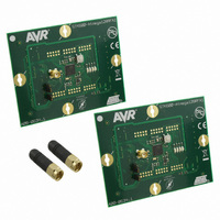
ATAVR128RFA1-EK1 Atmel, ATAVR128RFA1-EK1 Datasheet

ATAVR128RFA1-EK1
Specifications of ATAVR128RFA1-EK1
ATMEGA128RFA1-EK1
Related parts for ATAVR128RFA1-EK1
ATAVR128RFA1-EK1 Summary of contents
Page 1
Features • High Performance, Low Power AVR • Advanced RISC Architecture - 135 Powerful Instructions – Most Single Clock Cycle Execution - 32x8 General Purpose Working Registers - Fully Static Operation - MIPS Throughput at 16 MHz ...
Page 2
Pin Configurations [PF2:ADC2:DIG2] [PF3:ADC3:DIG4] [PF4:ADC4:TCK] [PF5:ADC5:TMS] [PF6:ADC6:TDO] [PF7:ADC7:TDI] [AVSS_RFP] [AVSS_RFN] [RSTN] [RSTON] [PG0:DIG3] [PG1:DIG1] [PG2:AMR] 2 Disclaimer ATmega128RFA1 2 Figure 1-1. Pinout ATmega128RFA1 Index corner ...
Page 3
Overview 3.1 Block Diagram 8266BS-MCU Wireless-03/11 The ATmega128RFA1 is a low-power CMOS 8-bit microcontroller based on the AVR enhanced RISC architecture combined with a high data rate transceiver for the 2.4 GHz ISM band derived from the ...
Page 4
... Watchdog timer, MAC symbol counter and 32.768kHz oscillator can be configured to continue to run. The device is manufactured using Atmel’s high-density nonvolatile memory technology. The On-chip ISP Flash allows the program memory to be reprogrammed in-system Figure 3-2 below ...
Page 5
... Software in the boot Flash section will continue to run while the application Flash section is updated, providing true Read-While-Write operation. By combining an 8 bit RISC CPU with In-System Self-Programmable Flash on a monolithic chip, the Atmel ATmega128RFA1 is a powerful microcontroller that provides a highly flexible and cost effective solution to many embedded control applications ...
Page 6
Port F (PF7...PF0) 3.2.11 Port G (PG5…PG0) 3.2.12 AVSS_RFP 3.2.13 AVSS_RFN 3.2.14 RFP 3.2.15 RFN 3.2.16 RSTN 3.2.17 RSTON 3.2.18 XTAL1 3.2.19 XTAL2 3.2.20 AREF 3.2.21 TST 3.2.22 CLKI 3.3 Unused Pins ATmega128RFA1 6 Port 8-bit ...
Page 7
Compatibility to ATmega1281/2561 3.4.1 Port A and Port C 3.4.2 External Memory Interface 3.4.3 High Voltage Programming Mode 3.4.4 AVR Oscillators and External Clock 3.4.5 Analog Frontend 8266BS-MCU Wireless-03/11 resistors can be enabled (in Reset all GPIO are configured ...
Page 8
Application Circuits 4.1 Basic Application Schematic ATmega128RFA1 8 A basic application schematic of the ATmega128RFA1 with a single-ended RF connector is shown in Figure 4-1 below on page 9. The 50Ω single-ended RF input is transformed to the 100Ω ...
Page 9
Table 4-1. Bill of Materials (BoM) Designator Description B1 SMD balun SMD balun / filter CB1 LDO VREG CB3 bypass capacitor CB2 Power supply bypass CB4 capacitor CX1, CX2 16MHz crystal load capacitor CX3, CX4 32.768kHz crystal load capacitor C1, ...
Page 10
ANT0 N2 LNA SW2 PA N1 SW1 ANT1 Pins TST & CLKI must be connected ATmega128RFA1 10 • RX/TX Indicator using alternate pin function DIG3/4 at Port G and F An extended feature set application schematic illustrating the use of ...
Page 11
Revision history Rev. 8266AS-MCU Wireless-12/09 Rev. 8266BS-MCU Wireless-03/11 8266BS-MCU Wireless-03/11 Please note that the referring page numbers in this section are referring to this document. The referring revision in this section are referring to the document revision 1. Initial ...
Page 12
Table of Contents ATmega128RFA1 12 1 Pin Configurations.............................................................................. 2 2 Disclaimer............................................................................................ 2 3 Overview .............................................................................................. 3 3.1 Block Diagram ........................................................................................................ 3 3.2 Pin Descriptions...................................................................................................... 5 3.3 Unused Pins ........................................................................................................... 6 3.4 Compatibility to ATmega1281/2561 ....................................................................... 7 4 Application Circuits ............................................................................ ...
Page 13
... INFORMATION) ARISING OUT OF THE USE OR INABILITY TO USE THIS DOCUMENT, EVEN IF ATMEL HAS BEEN ADVISED OF THE POSSIBILITY OF SUCH DAMAGES. Atmel makes no representations or warranties with respect to the accuracy or completeness of the contents of this document and reserves the right to make changes to specifications and product descriptions at any time without notice. Atmel does not make any commitment to update the information contained herein. Unless specifically provided otherwise, Atmel products are not suitable for, and shall not be used in, automotive applications. Atmel’ ...


