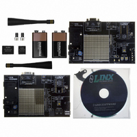
MDEV-916-ES-RS232 Linx Technologies Inc, MDEV-916-ES-RS232 Datasheet - Page 5

MDEV-916-ES-RS232
Manufacturer Part Number
MDEV-916-ES-RS232
Description
KIT MASTER DEV 916MHZ ES RS232
Manufacturer
Linx Technologies Inc
Series
ESr
Type
Transmitterr
Specifications of MDEV-916-ES-RS232
Frequency
916MHz
Product
RF Development Tools
Maximum Frequency
916 MHz
Supply Voltage (max)
9 V
Lead Free Status / RoHS Status
Lead free / RoHS Compliant
For Use With/related Products
ES Series RF Modules - 916MHz
Lead Free Status / Rohs Status
Lead free / RoHS Compliant
Other names
MDEV-916-ES-232
MDEV-916-ES-232
MDEV-916-ES-232
MASTER DEVELOPMENT SOFTWARE
USING THE BOARDS AS A DESIGN REFERENCE
ABOUT ANTENNAS
Page 8
The development system is supplied
with Windows-based software that
facilitates communication with the
development boards through the Host
Interface Module. This software allows
for
implementation of the modules as a
wireless serial link. The user selects
either a USB or RS232 connection and
whether the connected board is the
transmitter or receiver. The user can
then send text, ASCII characters, and even a picture. Documentation for the
software may be found by going to the 'Help' menu then 'Help File'.
Terminal emulation programs, such as HyperTerminal, do not provide error
correction; therefore, bit errors or data line hashing will be displayed as random
characters. Some form of error detection should be employed when developing
a protocol for wireless environments (please see Application Note AN-00160).
The master development boards included in this kit are very simple, yet they
illustrate some important techniques that you may wish to incorporate into your
own board layout. You will observe that the HP3 mounting pads (SMD version)
extend slightly past the edge of the part. This eases hand assembly and allows
for better heat conduction under the part if rework is necessary. Next, observe
the use of a full ground plane fill on the lower side of the board. This ground
plane serves three important purposes:
First, since a 1/4-wave antenna is employed, the ground plane is critical to serve
as a counterpoise (you may wish to read Application Note AN-00500 Antennas:
Design, Application, and Performance for additional details on how a ground
plane affects antenna function).
Second, a ground plane will suppress the transfer of noise between stages of a
product, as well as unintentional radiation of noise into free space.
Third, a ground plane allows for the implementation of a microstrip feed to the
antenna. The term microstrip refers to a PCB trace running over a ground plane
that is designed to serve as a 50-ohm transmission line between the module and
the antenna. A microstrip is implemented on this evaluation board. If you are
unfamiliar with microstrip calculations, you may wish to refer to the HP3 Series
Data Guides or the calculator available on the Linx Technologies website.
The choice of antennas is one of the most critical and often overlooked design
considerations. The range, performance, and legality of an RF link are critically
dependent upon the type of antenna employed. Linx offers a variety of antenna
styles that you may wish to consider for your design. Included with your kit is a
Linx CW Series connectorized whip antenna that should be connected prior to
using the kit. Despite the fact that the antenna is not centered on the board’s
ground plane, it exhibits a VSWR of <1.7 and suitably demonstrates the
module’s best practical performance.
testing
and
illustrates
basic
Figure 7: Master Development Software
ONLINE RESOURCES
Figure 8: Host Interface Module Schematics
www.linxtechnologies.com
3.3uF
3.3uF
C3
C4
• Latest News
• Data Guides
• Application Notes
• Knowledgebase
• Software Updates
If you have questions regarding any Linx product and have Internet access,
make www.linxtechnologies.com your first stop. Our website is organized in an
intuitive format to immediately give you the answers you need. Day or night, the
Linx website gives you instant access to the latest information regarding the
products and services of Linx. It’s all here: manual and software updates,
application notes, a comprehensive knowledgebase, FCC information, and much
more. Be sure to visit often!
C5
3.3uF
J2
3.3uF
GND
C1
+
+
GND
+
+
GND
VCC
DAT+
DAT -
GND
USB-B
5V
1
2
3
4
5
6
7
8
U1
MAX232
4
3
2
1
C1+
V+
C1-
C2+
C2-
V-
T2OUT
R2IN
GND
GND
RS232 HOST INTERFACE BOARD
USB HOST INTERFACE BOARD
1
2
3
4
5
6
7
8
R1OUT
R2OUT
T1OUT
U1
GND
R1IN
VCC
T1IN
T2IN
USBDP
USBDM
GND
VCC
SUSP_IND
RX_IND
TX_IND
485_TX
16
15
14
13
12
11
10
9
GND
TX RS232
RX RS232
PDN
SDM-USB-QS-S
VCC
®
GND
+
DATA_OUT
DATA_IN
C2
4.7uF
DCD
DSR
RTS
CTS
DTR
RI
16
15
14
13
12
11
10
9
TR SEL
RX DATA
TX DATA
TRSEL
PDN
GND
1
6
2
7
3
8
4
9
5
J2
RS-232
GND
GND
1
2
3
4
5
6
7
8
GND
VCC
GND
J1
GND
NC
NC
NC
VCC
NC
NC
GND
1
2
3
4
5
6
7
8
HIB-DIPMODULE
J1
HIB-DIPMODULE
GND
NC
NC
NC
VCC
NC
NC
GND
RTS/TRSEL
DTR/PDN
RX DATA
TX DATA
RTS/TRSEL
GND
GND
RX DATA
DTR/PDN
TX DATA
NC
NC
GND
GND
NC
NC
16
15
14
13
12
11
10
9
16
15
14
13
12
11
10
9
GND
RX DATA
TX DATA
TRSEL
PDN
GND
GND
GND
RX RS232
TX RS232
TR SEL
PDN
Page 9


