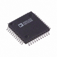
AD6640AST Analog Devices Inc, AD6640AST Datasheet - Page 22

AD6640AST
Manufacturer Part Number
AD6640AST
Description
IC ADC 12BIT 65MSPS 44-LQFP
Manufacturer
Analog Devices Inc
Datasheet
1.AD6640STPCB.pdf
(24 pages)
Specifications of AD6640AST
Rohs Status
RoHS non-compliant
Function
A/D Converter
Rf Type
Cellular/PCS, GPS
Secondary Attributes
12 Bit, 65MSPS
Package / Case
44-LQFP
Available stocks
Company
Part Number
Manufacturer
Quantity
Price
Company:
Part Number:
AD6640AST
Manufacturer:
AD
Quantity:
13 888
Company:
Part Number:
AD6640AST
Manufacturer:
ADI
Quantity:
240
Part Number:
AD6640ASTZ
Manufacturer:
ADI/亚德诺
Quantity:
20 000
AD6640
In narrow-band applications, harmonics of the ADC can be
placed out-of-band. One example is the digitization of a
201 MHz IF signal using a 17.333 MHz clock. As shown in
Figure 33, the spurious performance has diminished due to
internal slew rate limitations of the ADC. However, the SNR of
the converter is still quite good. Subsequent digital filtering with
a channelizer chip such as the AD6620 will yield even better SNR.
For multicarrier applications, third order intercept of the drive
amplifier is important. If the input network is matched to the
internal 900 Ω input impedance, the required full-scale drive
level is –3 dBm. If spurious products delivered to the ADC are
required to be below –90 dBFS, the typical performance of the
ADC with dither applied, then the required third order intercept
point for the drive amplifier can be calculated.
For multicarrier applications, the AD6640 is useful up to about
80 MHz analog in. For single channel applications, the AD6640
is useful to 200 MHz as shown in the bandwidth charts. In
either case, many common IF frequencies exist in this range of
frequencies. If the ADC is used to sample these signals, they will
be aliased down to baseband during the sampling process in
much the same manner that a mixer will down-convert a signal.
For signals in various Nyquist zones, the following equations
may be used to determine the final frequency after aliasing.
Using the converter to alias down these narrow-band or wide-
band signals has many potential benefits. First and foremost is
the elimination of a complete mixer stage along with amplifiers,
filters, and other devices, reducing cost and power dissipation. In
some cases, the elimination of two IF stages is possible.
TPCs 15 and 18 illustrate a multicarrier, IF sampling system. By
using dither, all spurious components are forced below 90 dBFS
(TPC 18). The dashed line illustrates how a 5 MHz band-pass
filter could be centered at 67.5 MHz. As discussed earlier, this
approach greatly reduces the size and complexity of the receiver’s
RF/IF section.
f
f
f
f
1NYQUISTS
2NYQUISTS
3NYQUISTS
4NYQUISTS
= f
= abs ( f
= 2 × f
= abs (2 × f
SAMPLE
SAMPLE
SAMPLE
− f
SAMPLE
SIGNAL
− f
− f
SIGNAL
SIGNAL
− f
SIGNAL
)
)
–22–
RECEIVE CHAIN FOR A PHASED-ARRAY CELLULAR
BASE STATION
The AD6640 is an excellent digitizer for beam forming in phased-
array antenna systems. The price performance of the AD6640
and AD6620 channelizers allows for a very competitive solution.
Phased-array base stations allow better coverage by focusing the
receivers’ sensitivity in the direction needed. Phased-array systems
allow for the electronic beam to form on the receive antennas.
A typical phased-array system may have eight antennas, as shown
in Figure 34. Since a typical base station will handle 32 calls,
each antenna would have to be connected to 32 receivers. If done
with analog or traditional radios, the system grows quite rapidly.
With a multicarrier receiver, however, the design is quite compact.
Each antenna would have a wideband down-converter with one
AD6640 per receiver. The output of each AD6640 would drive
32 AD6620 channelizers, which are phase locked in groups of
eight—one per antenna. This allows each group of eight AD6620s
to tune and lock onto a different user. When the incoming signal
direction is determined, the relative phase of each AD6620 in
the group can be adjusted so that the output signals sum together
in a constructive manner, giving high gain and directivity in the
direction of the caller. This application would not be possible
with traditional receiver designs.
100
40
60
80
20
0
Figure 33. IF Sampling a 201 MHz Input
198
ANALOG IF
FILTER MASK
199.8
201.6
FREQUENCY – MHz
ALIASED
SIGNALS
ALIASED
SECOND HARMONIC
203.4
ALIASED
THIRD HARMONIC
205.2
207
REV. A


