SI4312-B10-GM Silicon Laboratories Inc, SI4312-B10-GM Datasheet
SI4312-B10-GM
Specifications of SI4312-B10-GM


Related parts for SI4312-B10-GM

SI4312-B10-GM Summary of contents
Page 1
... Home automation and security Description The Si4312 is a fully-integrated OOK CMOS RF receiver that operates in the unlicensed 315 and 433.92 MHz ultra high frequency (UHF) bands designed for high-volume, cost-sensitive RF receiver applications, such as set-top box RF receivers, remote controls, garage door openers, home automation, security, remote keyless entry systems, wireless POS, and telemetry ...
Page 2
... Si4312 2 Rev. 0.5 ...
Page 3
... Crystal Oscillator . . . . . . . . . . . . . . . . . . . . . . . . . . . . . . . . . . . . . . . . . . . . . . . . . . . .13 3.10. Reset Pin . . . . . . . . . . . . . . . . . . . . . . . . . . . . . . . . . . . . . . . . . . . . . . . . . . . . . . . . . 13 4. Pin Descriptions: Si4312-B10- Ordering Guide . . . . . . . . . . . . . . . . . . . . . . . . . . . . . . . . . . . . . . . . . . . . . . . . . . . . . . . . . . 15 6. Package Markings (Top Marks 6.1. Si4312 Top Mark . . . . . . . . . . . . . . . . . . . . . . . . . . . . . . . . . . . . . . . . . . . . . . . . . . . . 16 6.2. Top Mark Explanation . . . . . . . . . . . . . . . . . . . . . . . . . . . . . . . . . . . . . . . . . . . . . . . . 16 7. Package Outline: Si4312-B10- PCB Land Pattern: Si4312-B10- Document Change List . . . . . . . . . . . . . . . . . . . . . . . . . . . . . . . . . . . . . . . . . . . . . . . . . . . . .21 Contact Information . . . . . . . . . . . . . . . . . . . . . . . . . . . . . . . . . . . . . . . . . . . . . . . . . . . . . . . .22 Rev. 0.5 Si4312 Page 3 ...
Page 4
... Exposure beyond recommended operating conditions for extended periods may affect device reliability. 2. The Si4312 device is a high-performance RF integrated circuit with certain pins having an ESD rating of < HBM. Handling and assembly of this device should only be done at ESD-protected workstations. ...
Page 5
... Reset asserted RST 3 3 500 µA OH OUT –500 µA OL OUT Symbol t SRST t SRST 70% 30% Figure 1. Reset Timing Rev. 0.5 Si4312 Min Typ Max Unit — 20 TBD mA — 2 TBD µA 0 — 0 –0.3 — 0 –10 — 10 µA –10 — 10 µA 0 — — — ...
Page 6
... Si4312 Table 5. Si4312 Receiver Characteristics = 50 Ω ° 3 Parameter –3 (Note 1) Sensitivity @ BER = 10 3 Data Rate Adjacent Channel Rejection (Note 1) ±200 kHz Alternate Channel Rejection 1,2 ±400 kHz 1,2 Image Rejection 128 kHz 1,2 Blocking 1,2 Maximum RF Input Power 3 Input IP3 3 LNA Input Capacitance ...
Page 7
... ANTENNA RATIO Figure 2. Si4312 OOK 433.92 MHz Application Schematic 2.1. Typical Application Bill of Materials Table 7. Si4312 Typical Application Bill of Materials Component(s) C1 Supply bypass capacitor, 22 nF, 20%, Z5U/X7R C2 Time constant capacitor, 1 µF C3 Antenna matching capacitor for 433.92 MHz and 62 nH for 315 MHz R1 Time constant resistor, 20 k ...
Page 8
... DSP implementation of the channel filters provides better repeatability and control of the bandwidth and frequency response of the filter compared to analog implementations. No off-chip ceramic filters are needed with the Si4312 as all IF channel filtering is performed in the digital domain. Rev. 0.5 Si4312 ...
Page 9
... Carrier Frequency Selection The Si4312 can be tuned to either 315 or 433.92 MHz by driving Pin 6 (315/434) to VDD or GND. The 315 MHz operation is chosen by driving Pin 6 (315/434) to VDD, and 433.92 MHz operation is chosen by driving Pin 6 (315/434) to GND. Table 8. Carrier Frequency Selection 3.4. Bit Time BT[1:0] Selection The Si4312 can operate with data rates kbps non-return to zero (NRZ) data or 5 kbps Manchester encoded data ...
Page 10
... OOK Waveform Figure 5. Example of the Threshold Calculation Ratio is a unit-less multiplier that relates the OFF time to the ON time. The Si4312 defines two constants for RATIO as shown in Table 10 based on the logic level of pin 5. Table 10. RATIO Constants Based on Logic Level of Pin 5 10 ...
Page 11
... The Si4312 uses a narrow channel bandwidth of 160 kHz and frequency scanning to obtain excellent sensitivity levels (– ...
Page 12
... Threshold Hold Time Selection The threshold hold time is defined as the length of time the Si4312 keeps its slicer threshold voltage level when no signals are present signal does not appear after this time interval, the Si4312 will re-start the frequency scan process and look for the signal in one of its three frequency bins ...
Page 13
... Reset Pin Driving the RST pin (pin 4) low will disable the Si4312 and place the device into reset mode. All active blocks in the device are powered off in this mode, bringing the current consumption to less than 10 uA. The Si4312 is enabled by driving the RST pin (pin 4) to VDD. Refer to Table 4 " ...
Page 14
... Si4312 4. Pin Descriptions: Si4312-B10-GM VDD RFGND RX_IN RST RATIO Pin Number(s) Name VDD 2 RFGND 3 RX_IN 4 RST 5 RATIO 6 315/434 7, 12, GND PAD GND 9 XTL1 10 XTL2 13 DOUT 14, 15 BT[1:0] 16, 17 TH[1:0] 18,19, BT0 3 14 GND PAD Description Supply voltage, may connect to external battery. ...
Page 15
... Ordering Guide Part Number* Si4312-B10-GM 315/433.92 MHz OOK Receiver *Note: Add an “(R)” at the end of the device part number to denote tape and reel option. Description Rev. 0.5 Si4312 Package Operating Type Temperature QFN – °C Pb-free 15 ...
Page 16
... Line 3 Marking: Circle = 0.5 mm Diameter (Bottom-Left Justified) YWW = Date Code Figure 7. Si4312 Top Mark Example 12 = Si4312 10 = Firmware Revision 1 Revision B Die Internal tracking code Pin 1 Identifier Assigned by the Assembly House. Corresponds to the last digit of the current year (Y) and the workweek (WW) of the mold date ...
Page 17
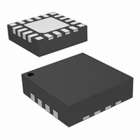
... Package Outline: Si4312-B10-GM Figure 8 illustrates the package details for the Si4312-B10-GM. Table 13 lists the values for the dimensions shown in the illustration. Figure 8. 20-Pin Quad Flat No-Lead (QFN) Symbol Millimeters Min Nom A 0.80 0.85 A1 0.00 0.02 b 0.20 0.25 c 0.27 0.32 D 3.00 BSC D2 1 ...
Page 18
... Si4312 8. PCB Land Pattern: Si4312-B10-GM Figure 9 illustrates the PCB land pattern details for the Si4312-B10-GM. Table 14 lists the values for the dimensions shown in the illustration. 18 Figure 9. PCB Land Pattern Rev. 0.5 ...
Page 19
... Card Assembly 10. A No-Clean, Type-3 solder paste is recommended. 11. The recommended card reflow profile is per the JEDEC/IPC J-STD-020 specification for small body components. Symbol Millimeters Min GE 2.10 W — X — Y 0.61 REF ZE — ZD — Rev. 0.5 Si4312 Max — 0.34 0.28 3.31 3.31 19 ...
Page 20
... Si4312 N : OTES 20 Rev. 0.5 ...
Page 21
... Removed I current spec when input = –30 dBm VDD from Table 3 "DC Characteristics" Updated sensitivity specs and test conditions in Table 5 "Si4312 Receiver Characteristics" Updated frequency scanning description in section “3.6. Frequency Scanning” Added reference clock drive capability to section “3.9. Crystal Oscillator” ...
Page 22
... Si4312 C I ONTACT NFORMATION Silicon Laboratories Inc. 400 West Cesar Chavez Austin, TX 78701 Tel: 1+(512) 416-8500 Fax: 1+(512) 416-9669 Toll Free: 1+(877) 444-3032 Email: wireless@silabs.com Internet: www.silabs.com The information in this document is believed to be accurate in all respects at the time of publication but is subject to change without notice. ...