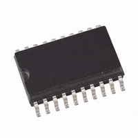
ATA8204P3-TKQY Atmel, ATA8204P3-TKQY Datasheet - Page 5

ATA8204P3-TKQY
Manufacturer Part Number
ATA8204P3-TKQY
Description
IC RCVR ASK/FSK UHF 433MHZ 20SSO
Manufacturer
Atmel
Datasheet
1.ATA8203P3-TKQY.pdf
(46 pages)
Specifications of ATA8204P3-TKQY
Frequency
433MHz
Sensitivity
-115dBm
Data Rate - Maximum
10 kbps
Modulation Or Protocol
ASK, FSK
Applications
General Purpose
Current - Receiving
8.5mA
Data Interface
PCB, Surface Mount
Antenna Connector
PCB, Surface Mount
Features
RSSI Equipped
Voltage - Supply
4.5 V ~ 5.5 V
Operating Temperature
-40°C ~ 85°C
Package / Case
20-SOIC (0.200", 5.30mm Width)
Pin Count
20
Screening Level
Industrial
Lead Free Status / RoHS Status
Lead free / RoHS Compliant
Memory Size
-
Lead Free Status / Rohs Status
Compliant
3. RF Front-end
9121B–INDCO–04/09
The RF front-end of the receiver is a low-IF heterodyne configuration that converts the input sig-
nal into about 1 MHz IF signal with a typical image rejection of 30 dB. According to Figure
1-2 on page 3
mixer, polyphase low-pass filter and an IF amplifier.
The PLL generates the drive frequency f
integrated low noise LC-VCO (Voltage Controlled Oscillator) and PLL-loop filter. The XTO (crys-
tal oscillator) generates the reference frequency f
or f
mixer drive frequency f
four circuit (f
f
pared with f
and thereby generates the control voltage for the VCO. If f
lated using the following formula:
f
bands.
The XTO is a two-pin oscillator that operates at the series resonance of the quartz crystal with
high current but low voltage signal, so that there is only a small voltage at the crystal oscillator
frequency at pins XTAL1 and XTAL2. According to
to GND with two capacitors C
these capacitors are recommended by the crystal supplier. Due to an inductive impedance at
steady state oscillation and some PCB parasitics, a lower value of C
necessary.
The value of C
f
find the right value for this capacitor.) When designing the system in terms of receiving band-
width and local oscillator accuracy, the accuracy of the crystal and the XTO must be considered.
Figure 3-1.
The nominal frequency f
using the following formula (low-side injection):
f
VCO
REF
XTO
LO
= f
REF
= f
and hence of f
is divided by a factor of 128 or 64 and feeds into a phase frequency detector and is com-
RF
LO
= f
– f
/128 for 868 MHz band, f
XTO
IF
REF
LO
/3 (315 MHz version). The integrated LC-VCO generates two or four times the
Lx
XTO Peripherals
the front-end consists of an LNA (Low Noise Amplifier), LO (Local Oscillator), I/Q
. The output of the phase frequency detector is fed into an integrated loop filter
= f
should be optimized for the individual board layout to achieve the exact value of
VCO
LO
. (The best way is to use a crystal with known load resonance frequency to
/2 for 868 MHz version, f
VCO
LO
. The I/Q signals for the mixer are generated with a divide by two or
is determined by the RF input frequency f
L1
and C
REF
TEST3
TEST2
XTAL2
XTAL1
DVCC
= f
L2
LO
ATA8203/ATA8204/ATA8205
LO
from XTAL1 and XTAL2 respectively. The value of
for the mixer using a fully integrated synthesizer with
/64 for 433 MHz bands, f
V
LO
S
REF
= f
Figure
VCO
= f
/4 for 433 MHz and 315 MHz versions).
XTO
C
C
L2
L1
3-1, the crystal should be connected
/2 (868 MHz and 433 MHz versions)
LO
is determined, f
RF
REF
and the IF frequency f
L1
= f
and C
LO
XTO
/64 for 315 MHz
L2
can be calcu-
is normally
Figure
IF
5


