ATMEGA64RZAV-10PU Atmel, ATMEGA64RZAV-10PU Datasheet
ATMEGA64RZAV-10PU
Specifications of ATMEGA64RZAV-10PU


Related parts for ATMEGA64RZAV-10PU


ATMEGA64RZAV-10PU Summary of contents
Page 1
... Features • High-performance, Low-power Atmel • Advanced RISC Architecture – 131 Powerful Instructions – Most Single-clock Cycle Execution – 32 × 8 General Purpose Working Registers – Fully Static Operation – MIPS Throughput at 20 MHz • High Endurance Non-volatile Memory segments – 64 Kbytes of In-System Self-programmable Flash program memory – ...
Page 2
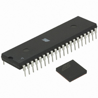
Pin Configurations Figure 1-1. Note: 2593NS–AVR–07/10 Pinout ATmega644 (PCINT8/XCK0/T0) PB0 (PCINT9/CLKO/T1) PB1 (PCINT10/INT2/AIN0) PB2 (PCINT11/OC0A/AIN1) PB3 (PCINT12/OC0B/SS) PB4 (PCINT13/MOSI) PB5 (PCINT14/MISO) PB6 (PCINT15/SCK) PB7 RESET VCC GND XTAL2 XTAL1 (PCINT24/RXD0) PD0 (PCINT25/TXD0) PD1 (PCINT26/INT0) PD2 (PCINT27/INT1) PD3 (PCINT28/OC1B) PD4 ...
Page 3
Disclaimer Typical values contained in this datasheet are based on simulations and characterization of other AVR microcontrollers manufactured on the same process technology. Min and Max values will be available after the device is characterized. 2. Overview The ATmega644 ...
Page 4
... Application Flash section is updated, providing true Read-While-Write operation. By combining an 8-bit RISC CPU with In-System Self-Programmable Flash on a monolithic chip, the Atmel ATmega644 is a powerful microcontroller that provides a highly flexible and cost effec- tive solution to many embedded control applications. The ATmega644 AVR is supported with a full suite of program and system development tools including: C compilers, macro assemblers, program debugger/simulators, in-circuit emulators, and evaluation kits ...
Page 5
As inputs, Port A pins that are externally pulled low will source current if the pull-up resistors are activated. The Port A pins are tri-stated when a reset condition becomes active, even if the clock is not ...
Page 6
AVCC AVCC is the supply voltage pin for Port F and the Analog-to-digital Converter. It should be exter- nally connected through a low-pass filter. CC 2.2.11 AREF This is the analog reference pin for the ...
Page 7
... Resources A comprehensive set of development tools, application notes and datasheetsare available for download on http://www.atmel.com/avr. 2593NS–AVR–07/10 ATmega644 7 ...
Page 8
Register Summary Address Name Bit 7 (0xFF) Reserved - (0xFE) Reserved - (0xFD) Reserved - (0xFC) Reserved - (0xFB) Reserved - (0xFA) Reserved - (0xF9) Reserved - (0xF8) Reserved - (0xF7) Reserved - (0xF6) Reserved - (0xF5) Reserved - ...
Page 9
Address Name Bit 7 (0xBF) Reserved - (0xBE) Reserved - (0xBD) TWAMR TWAM6 (0xBC) TWCR TWINT (0xBB) TWDR (0xBA) TWAR TWA6 (0xB9) TWSR TWS7 (0xB8) TWBR (0xB7) Reserved - (0xB6) ASSR - (0xB5) Reserved - (0xB4) OCR2B (0xB3) OCR2A (0xB2) ...
Page 10
Address Name Bit 7 (0x7D) Reserved - (0x7C) ADMUX REFS1 (0x7B) ADCSRB - (0x7A) ADCSRA ADEN (0x79) ADCH (0x78) ADCL (0x77) Reserved - (0x76) Reserved - (0x75) Reserved - (0x74) Reserved - (0x73) PCMSK3 PCINT31 (0x72) Reserved - (0x71) Reserved ...
Page 11
Address Name Bit 7 0x1B (0x3B) PCIFR - 0x1A (0x3A) Reserved - 0x19 (0x39) Reserved - 0x18 (0x38) Reserved - 0x17 (0x37) TIFR2 - 0x16 (0x36) TIFR1 - 0x15 (0x35) TIFR0 - 0x14 (0x34) Reserved - 0x13 (0x33) Reserved - ...
Page 12
Instruction Set Summary Mnemonics Operands ARITHMETIC AND LOGIC INSTRUCTIONS ADD Rd, Rr Add two Registers ADC Rd, Rr Add with Carry two Registers ADIW Rdl,K Add Immediate to Word SUB Rd, Rr Subtract two Registers SUBI Rd, K Subtract ...
Page 13
Mnemonics Operands BRVC k Branch if Overflow Flag is Cleared BRIE k Branch if Interrupt Enabled BRID k Branch if Interrupt Disabled BIT AND BIT-TEST INSTRUCTIONS SBI P,b Set Bit in I/O Register CBI P,b Clear Bit in I/O Register ...
Page 14
Mnemonics Operands OUT P, Rr Out Port PUSH Rr Push Register on Stack POP Rd Pop Register from Stack MCU CONTROL INSTRUCTIONS NOP No Operation SLEEP Sleep WDR Watchdog Reset BREAK Break 2593NS–AVR–07/10 Description P ← Rr STACK ← Rr ...
Page 15
... Note: 1. This device can also be supplied in wafer form. Please contact your local Atmel sales office for detailed ordering information and minimum quantities. 2. Pb-free packaging, complies to the European Directive for Restriction of Hazardous Substances (RoHS directive). Also Halide free and fully Green. ...
Page 16
Packaging Information 7.1 44A PIN 0˚~7˚ L Notes: 1. This package conforms to JEDEC reference MS-026, Variation ACB. 2. Dimensions D1 and E1 do not include mold protrusion. Allowable protrusion is 0.25 mm per side. Dimensions ...
Page 17
A SEATING PLANE Notes: 1. This package conforms to JEDEC reference MS-011, Variation AC. 2. Dimensions D and E1 do not include mold Flash or Protrusion. Mold Flash or Protrusion shall not exceed 0.25 mm ...
Page 18
... D Marked Pin TOP VIEW BOTTOM VIEW Note: JEDEC Standard MO-220, Fig. 1 (SAW Singulation) VKKD-3. Package Drawing Contact: packagedrawings@atmel.com 2593NS–AVR–07/10 E Pin #1 Corner Pin #1 Option A 1 Triangle 2 3 Option B Pin #1 Chamfer (C 0.30) Option C Pin #1 Notch e (0.20 R) TITLE 44M1, 44-pad 1.0 mm Body, Lead Pitch 0 ...
Page 19
Errata 8.1 Rev. C • Inaccurate ADC conversion in differential mode with 200× gain 1. Inaccurate ADC conversion in differential mode with 200× gain With AVCC < 3.6V, random conversions will be inaccurate. Typical absolute accuracymay reach 64 LSB. ...
Page 20
... Corrected use of comma in example under tion (percentage) in Active and Idle mode,” on page 332 Note 6 and Note 7 in Table 26-5, “2-wire Serial Bus Requirements,” on page 321 been removed Updated document according to Atmel standard use of technical terminology Updated ”Features” on page 1. Updated description in ” ...
Page 21
Rev. 2593J - 09/ 9.6 Rev. 2593I - 08/ 9.7 Rev. 2593H - 07/ 9.8 Rev. 2593G - 06/ 9.9 Rev. 2593F - 04/06 ...
Page 22
Rev. 2593D - 04/ 9.12 Rev. 2593C - 03/ 9.13 Rev. 2593B - 03/ 10. 11. 12. 13. 14. 15. 16. 17. ...
Page 23
... Disclaimer: The information in this document is provided in connection with Atmel products. No license, express or implied, by estoppel or otherwise, to any intellectual property right is granted by this document or in connection with the sale of Atmel products. EXCEPT AS SET FORTH IN ATMEL’S TERMS AND CONDI- TIONS OF SALE LOCATED ON ATMEL’S WEB SITE, ATMEL ASSUMES NO LIABILITY WHATSOEVER AND DISCLAIMS ANY EXPRESS, IMPLIED OR STATUTORY WARRANTY RELATING TO ITS PRODUCTS INCLUDING, BUT NOT LIMITED TO, THE IMPLIED WARRANTY OF MERCHANTABILITY, FITNESS FOR A PARTICULAR PURPOSE, OR NON-INFRINGEMENT ...