EM351-MOD-LR-ANT-TG Ember, EM351-MOD-LR-ANT-TG Datasheet - Page 149
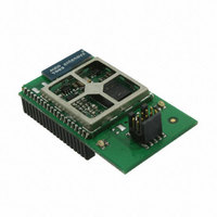
EM351-MOD-LR-ANT-TG
Manufacturer Part Number
EM351-MOD-LR-ANT-TG
Description
MODULE EM351 PA/LNA W/ANT TG
Manufacturer
Ember
Specifications of EM351-MOD-LR-ANT-TG
Frequency
2.4GHz
Data Rate - Maximum
250kbps
Modulation Or Protocol
802.15.4 Zigbee
Voltage - Supply
2.1 V ~ 3.6 V
Current - Receiving
26mA
Current - Transmitting
31mA
Data Interface
PCB, Surface Mount
Memory Size
128kB Flash, 12kB RAM
Antenna Connector
On-Board, Chip
Operating Temperature
-40°C ~ 85°C
Package / Case
Module
Lead Free Status / RoHS Status
Lead free / RoHS Compliant
Power - Output
-
Applications
-
Sensitivity
-
Other names
636-1016


A rising edge on TI1 enables the counter and sets the INT_TIMTIF flag. The counter then counts on ETR rising
edges. The delay between the rising edge of the ETR signal and the actual reset of the counter is due to the
resynchronization circuit on ETRP input.
9.3.14 Timer Synchronization
The two timers can be linked together internally for timer synchronization or chaining. A timer configured in
master mode can reset, start, stop or clock the counter of the other timer configured in slave mode.
Figure 9-31 presents an overview of the trigger selection and the master mode selection blocks.
9.3.14.1
For example, to configure Timer 1 to act as a prescaler for Timer 2:
Note: If OCy is selected on Timer 1 as trigger output (TIM_MMS = 1xx), its rising edge is used to clock the
counter of Timer 2.
Configure Timer 1 in master mode so that it outputs a periodic trigger signal on each UEV. Writing
TIM_MMS = 010 in the TIM1_CR2 register causes a rising edge to be output on TRGO each time a UEV is
generated.
To connect the TRGO output of Timer 1 to Timer 2, configure Timer 2 in slave mode using ITR0 as an
internal trigger. Write TIM_TS = 100 in the TIM2_SMCR register.
Put the slave mode controller in external clock mode 1: Write TIM_SMS = 111 in the TIM2_SMCR register.
This causes Timer 2 to be clocked by the rising edge of the periodic Timer 1 trigger signal, which
corresponds to the Timer 1 counter overflow.
Finally, enable both timers: Set their respective TIM_CEN bits in the TIMx_CR1 register.
Using One Timer as Prescaler for the Other Timer
Figure 9-30. Control circuit in External Clock Mode 2 + Trigger Mode
Figure 9-31. Master/Slave Timer Example
Final
9-25
120-035X-000G
Related parts for EM351-MOD-LR-ANT-TG
Image
Part Number
Description
Manufacturer
Datasheet
Request
R

Part Number:
Description:
MODULE EM351 NO PA/LNA W/ANT TG
Manufacturer:
Ember
Datasheet:

Part Number:
Description:
MODULE EM351 NO PA/LNA W/RF CONN
Manufacturer:
Ember
Datasheet:

Part Number:
Description:
MODULE EM351 PA/LNA W/RF CONN
Manufacturer:
Ember
Datasheet:

Part Number:
Description:
KIT DEV EMBER ZIGBEE W/PCWH
Manufacturer:
Custom Computer Services Inc (CCS)

Part Number:
Description:
PROGRAMMER USB FLASH EM250/260
Manufacturer:
Ember
Datasheet:

Part Number:
Description:
IC ZIGBEE SYSTEM-ON-CHIP 40-QFN
Manufacturer:
Ember
Datasheet:

Part Number:
Description:
IC ZIGBEE SYSTEM-ON-CHIP 48-QFN
Manufacturer:
Ember
Datasheet:
Part Number:
Description:
IC RF TXRX ZIGBEE 128KB 48QFN
Manufacturer:
Ember
Datasheet:
Part Number:
Description:
IC RF TXRX ZIGBEE 192KB 48QFN
Manufacturer:
Ember
Datasheet:

Part Number:
Description:
INSIGHT ADAPTER FOR EM2XX
Manufacturer:
Ember
Datasheet:

Part Number:
Description:
IAR EWARM LICENCE FOR EM35X
Manufacturer:
Ember
Datasheet:

Part Number:
Description:
KIT EVAL EM250 RF TEST
Manufacturer:
Ember
Datasheet:

Part Number:
Description:
INSIGHT ADAPTER 3 FOR EM35X
Manufacturer:
Ember
Datasheet:

Part Number:
Description:
EM250 RCM BOARD
Manufacturer:
Ember
Datasheet:

Part Number:
Description:
EM35X BREAKOUT BOARD
Manufacturer:
Ember
Datasheet: