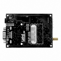
2200-00122 Laird Technologies, 2200-00122 Datasheet

2200-00122
Specifications of 2200-00122
Related parts for 2200-00122
2200-00122 Summary of contents
Page 1
CL4490-1000 Industrial 900MHz ConnexLink User’s Manual Version 1.4 11160 THOMPSON AVE LENEXA, KS 66219 (800) 492-2320 www.aerocomm.com sales@aerocomm.com ...
Page 2
Document Information Copyright © 2004 A Copyright The information contained in this manual and the accompanying Information software programs are copyrighted and all rights are reserved Inc. A ERO OMM periodic modifications of this product without ...
Page 3
FCC Information FCC Notice WARNING: This device complies with Part 15 of the FCC Rules. Operation is subject to the following two conditions: (1) This device may not cause harmful interference and (2) This device must accept any interference received, ...
Page 4
Table of Contents USER’S MANUAL .............................................................................................................................. 4 FIGURES ............................................................................................................................... 4 TABLES 1. CL4490 RF TRANSCEIVER....................................................................................... 5 1.1 O ........................................................................................................... 5 VERVIEW 1.2 CL4490 S PECIFICATION 1.3 CL4490 I ............................................................................................. 7 NTERFACE 2. INTERFACING PROTOCOL .................................................................................. 10 1.4 RS-232 .............................................................................................................. 11 ...
Page 5
CL4490 User’s Manual 1. CL4490 RF Transceiver The CL4490 transceiver is a Frequency-Hopping Spread Spectrum (FHSS) radio designed for license-free operation in the 900MHz ISM band. Out-of-the box, the radio sustains a standard asynchronous serial data stream between two or ...
Page 6
CL4490 User’s Manual 1.2 CL4490 Specification Specifications CL4490 - 1000 TRANSCEIVER PERFORMANCE Output power 1000mW Transmission range Up to 1500 feet (450m) indoors miles (32 km) line-of-sight Data rate Up to 115.2 Kbps RF Data Rate 76.8kbps ...
Page 7
CL4490 User’s Manual 1.3 CL4490 Interface The CL4490 supports RS-232/RS-485 (2-wire Half Duplex) protocols. By definition, RS-485 protocol can tolerate high noise and push signals over long cable lengths. When using cables, RS-485 will communicate as far as 4000feet (1200m) ...
Page 8
CL4490 User’s Manual RS-232 Pin Assignments Figure 2- RS-232 CL4490 Back View RS-485 (2-wire Half Duplex) Terminal Block Pin Assignments Figure 3- RS-485 CL4490 Back View Terminal Block 1 6 Note: Standard power is applied through ...
Page 9
CL4490 User’s Manual CL4490 Mechanical Diagram 1.170 0.536 0.060 0.000 2.750 2.375 9 Pin Male D-Connector Power Jack w/ 0.100 dia. pin and 0.250 opening, pin is PWR. 0.375 0.000 10/3/2005 Figure 4- CL4490 Mechanical Diagram Side View Label Recess, ...
Page 10
CL4490 User’s Manual 2. Interfacing Protocol The CL4490 is a DCE (Data Communications Equipment). A DCE can be interfaced to a DTE using a straight through serial cable (the serial cable provided with the CL4490 is a straight through cable). ...
Page 11
CL4490 User’s Manual 1.4 RS-232 RS-232 is a single ended data transmission protocol. The RS-232 signals are represented by voltage levels with respect to a system common (power / logic ground). The "idle" state (MARK) has the signal level negative ...
Page 12
CL4490 User’s Manual Figure 7- DCE to DCE Interface OEM Host CTS RTS RXD TXD GND DCD DSR DTR RI DCE Note: The Straight Through Cable provided with the CL4490 has female connectors on both ends and the Crossover cable ...
Page 13
CL4490 User’s Manual 1.6 Hardware Flow Control Flow control refers to the control of data flow between the host and the CL4490 the method used to handle data in the transmit/receive buffer of the CL4490 interface, and determines ...
Page 14
CL4490 User’s Manual 3. Network Topologies Topology refers to the shape of a network, or the network's layout. How different nodes in a network are connected to each other and how they communicate, is determined by the network's topology. The ...
Page 15
CL4490 User’s Manual 4. CL4490/CN4490 Configuration Utility Software AeroComm provides the easy to use CL4490/CN4490 Utility Software for programming the CL4490/CN4490. The GUI based software does not require any hardware configuration and works by itself. The software is compatible with ...
Page 16
CL4490 User’s Manual 4.2.1 CL4490 Settings The CL4490 Settings Page is shown below will appear the first time the program is run. 4.2.1.1 ConnexLink Settings Client/Server: Designates CL4490 type. In each network, there must be only one Server. ...
Page 17
CL4490 User’s Manual Max Transmit Retries (For Clients and Servers in Point-to-Point networks only): This value represents the maximum number of times a particular data packet will be transmitted unsuccessfully, or without an acknowledgement, before the CL4490 discards the packet. ...
Page 18
CL4490 User’s Manual Full Duplex: This mode restricts Client radios to transmitting on odd numbered frequency hop bins and the Server to even numbered frequency hop bins. Though the RF hardware is still technically half duplex, it makes the transceiver ...
Page 19
CL4490 User’s Manual 4.2.2 CN4490 Settings The CN4490 Settings Page is shown below will appear the first time when the CN4490 check box is checked. 4.2.2.1 CN4490 Settings Client/Server: Designates CN4490 type. In each network, there must be ...
Page 20
CL4490 User’s Manual Broadcast Attempts (For Servers in Point-to-Multipoint networks only): This value represents the number of times a data packet will be transmitted by the Server ConnexLink. The default value is 4 attempts. If communication is lost and the ...
Page 21
CL4490 User’s Manual 4.2.2.3 PC Settings IP Address: IP Address of the CN4490 unit. Port: Port number of the CN4490 unit, the Port number is always 2101. System Config: Type of CN4490 network to be configured. Valid choices are Point-to-Point ...
Page 22
CL4490 User’s Manual 5. Troubleshooting Problem Read Radio 1. Make sure the PC Settings are right. See Section 4.2.3 PC Settings. displays error message: “Radio not 2. Make sure the CL4490 unit uses the right serial responding.” cable. Refer to ...


