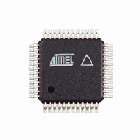
AT86RF211SAH-R Atmel, AT86RF211SAH-R Datasheet - Page 14

AT86RF211SAH-R
Manufacturer Part Number
AT86RF211SAH-R
Description
IC RF TXRX FSK 400-950MHZ 48TQFP
Manufacturer
Atmel
Datasheet
1.AT86RF211SDK.pdf
(66 pages)
Specifications of AT86RF211SAH-R
Frequency
400MHz ~ 950MHz
Data Rate - Maximum
100kbps
Modulation Or Protocol
FSK
Applications
ISM
Power - Output
7dBm ~ 12dBm
Sensitivity
-107dBm
Voltage - Supply
2.4 V ~ 3.6 V
Data Interface
PCB, Surface Mount
Antenna Connector
PCB, Surface Mount
Operating Temperature
-40°C ~ 85°C
Package / Case
48-TQFP Exposed Pad, 48-eTQFP, 48-HTQFP, 48-VQFP
Lead Free Status / RoHS Status
Contains lead / RoHS non-compliant
Memory Size
-
Current - Transmitting
-
Current - Receiving
-
2.2
2.2.1
2.2.2
14
Receiver Description
AT86RF211S
Overview and Choice of Intermediate Frequencies
Rx/Tx Switch
Figure 2-5.
For selectivity and flexibility purposes, a classic and robust 2 IF super-heterodyne archi-
tecture has been selected for the AT86RF211S. To minimize the cost of the external
components, the most popular IF values have been chosen. The impedances of the
input/output of the mixing stages have been internally matched to the most common
ceramic filter impedances.
Two typical IF values are suggested:
Note:
An SPST switch is integrated. In transmission mode, it protects the LNA input from the
large voltage swings of the Power Amplifier (PA) output (up to several volts peak-to-
peak), which is switched to a high impedance state. The SPST switch is automatically
turned on or off by the Rx/Tx control bit. The insertion loss is approximately 4 dB and the
reverse isolation about 30 dB in a 300Ω environment.
• 10.7 MHz is the most popular option (used with a 10.245 or 20.5 MHz crystal).
• 21.4 MHz (used with a 20.945 MHz crystal): the image frequency is far enough from
Data Rate
the carrier frequency to enable use of a front-end ceramic filter instead of a SAW
filter. Furthermore, 21.4 MHz quartz filters usually have more abrupt slopes than
10.7 MHz ceramic filters.
Medium
High
Low
IF1 can be any frequency but must match available ceramic filters.
Choosing the Loop Filter Values
220 pF
100 pF
560 pF
C1
Pin 41
FILT1
2.2 nF
5.6 nF
C1
1 nF
C2
14.7 kΩ
3.3 kΩ
10 kΩ
C2
R1
R1
VCOIN
Pin 42
For high modulation rate
For improvement of
phase noise
Comment
Typical
5348B–WIRE–03/06


