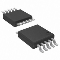
ATA8404-6DQY Atmel, ATA8404-6DQY Datasheet - Page 16

ATA8404-6DQY
Manufacturer Part Number
ATA8404-6DQY
Description
IC TRANSMITTR ASK/FSK UHF 10TSSO
Manufacturer
Atmel
Datasheet
1.ATA8405-6DQY.pdf
(20 pages)
Specifications of ATA8404-6DQY
Frequency
313MHz ~ 317MHz
Applications
Home Automation, Remote Sensing, RKE
Modulation Or Protocol
ASK, FSK
Data Rate - Maximum
40 kBaud
Power - Output
4dBm ~ 8dBm
Current - Transmitting
8.4mA
Data Interface
PCB, Surface Mount
Antenna Connector
PCB, Surface Mount
Voltage - Supply
2 V ~ 3.6 V
Operating Temperature
-55°C ~ 85°C
Package / Case
10-TSSOP
Operating Temperature (max)
85C
Operating Temperature Classification
Industrial
Operating Supply Voltage (typ)
2.5/3.3V
Operating Supply Voltage (max)
3.6V
Lead Free Status / RoHS Status
Lead free / RoHS Compliant
Features
-
Memory Size
-
Lead Free Status / Rohs Status
Compliant
7. Electrical Characteristics (Continued)
V
Typical values are given at V
C
16
S
M
Parameters
Real part of XTO1 impedance in
small signal oscillation
Crystal oscillator start-up time
XTO drive current
Locking time of the PLL
PLL loop bandwidth
In loop phase noise PLL
Phase noise VCO
Frequency range of VCO
Clock output frequency (CMOS
microcontroller compatible)
Clock output minimum High and
Low time
Series resonance resistance of
the resonator seen from pin
XTO1
Capacitive load at Pin XTO1
FSK modulation frequency rate
FSK switch OFF resistance
FSK switch OFF capacitance
FSK switch ON resistance
ASK modulation frequency rate
= 2.0V to 3.6V, T
= 4.37 fF, C
ATA8404/ATA8405 [Preliminary]
0
= 1.3 pF, C
amb
= –40°C to +85°C unless otherwise specified.
LNOM
S
= 3.0V and T
= 18 pF, C
Test Conditions
This value is important for crystal
oscillator start-up
Time between ENABLE of the IC with
FSK = H and activation of the CLK
output. The CLK is activated
synchronously to the output frequency
if the current through the XTAL has
reached 35% to 80% of its maximum
amplitude. Crystal parameters:
C
C
R
Current flowing through the crystal in
steady state oscillation (peak-to-peak
value)
Time between the activation of CLK
and when the PLL is locked
(transmitter ready for data
transmission)
25 kHz distance to carrier
at 1 MHz
at 36 MHz
ATA8404
ATA8405
ATA8404
ATA8405
C
Low = 0.2
For proper detection of the XTO
amplitude
This corresponds to 20 kBaud in
Manchester coding and 40 kBaud in
NRZ coding
High Z
High Z capacitance
Low Z
Duty cycle of the modulation signal =
50%, this corresponds to 20 kBaud in
Manchester coding and 40 kBaud in
NRZ coding
M
LNOM
S
Load
= 4.37 fF, C
60
amb
4
= 10 pF, C
= 18 pF, C
20 pF, High = 0.8
= 25°C. All parameters are referred to GND (pin 9).
V
S
0
, f
= 1.3 pF,
5
4
CLK
= 15 pF and R
= 10 pF, C
< 1.7 MHz
Vs,
5
= 15 pF,
S
60
R
C
R
Symbol
f
f
f
MOD_FSK
MOD_ASK
Loop_PLL
T
C
SWIT_OFF
SWIT_OFF
RE
R
L
SWIT_ON
I
L
L
f
DXTO
f
CLKLH
T
at36M
L_max
T
VCO
s_max
at1M
CLK
PLL
XTO
XTO
PLL
–650
Min.
0.75
310
432
125
50
0
0
–1100
f
f
–121
Typ.
0
0
300
250
–85
–90
130
0.6
0.9
/192
/256
Max.
–115
250
–76
–84
317
448
150
175
1.1
9136C–INDCO–10/09
1.4
20
20
5
dBc/Hz
dBc/Hz
dBc/Hz
µApp
Unit
MHz
MHz
MHz
kHz
kHz
kHz
ms
pF
pF
µs
ns
k


