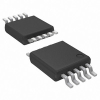
ATA8404-6DQY Atmel, ATA8404-6DQY Datasheet - Page 7

ATA8404-6DQY
Manufacturer Part Number
ATA8404-6DQY
Description
IC TRANSMITTR ASK/FSK UHF 10TSSO
Manufacturer
Atmel
Datasheet
1.ATA8405-6DQY.pdf
(20 pages)
Specifications of ATA8404-6DQY
Frequency
313MHz ~ 317MHz
Applications
Home Automation, Remote Sensing, RKE
Modulation Or Protocol
ASK, FSK
Data Rate - Maximum
40 kBaud
Power - Output
4dBm ~ 8dBm
Current - Transmitting
8.4mA
Data Interface
PCB, Surface Mount
Antenna Connector
PCB, Surface Mount
Voltage - Supply
2 V ~ 3.6 V
Operating Temperature
-55°C ~ 85°C
Package / Case
10-TSSOP
Operating Temperature (max)
85C
Operating Temperature Classification
Industrial
Operating Supply Voltage (typ)
2.5/3.3V
Operating Supply Voltage (max)
3.6V
Lead Free Status / RoHS Status
Lead free / RoHS Compliant
Features
-
Memory Size
-
Lead Free Status / Rohs Status
Compliant
4.2
4.2.1
4.2.2
9136C–INDCO–10/09
Transmission with ENABLE = High
FSK Mode
ASK Mode
The ATA8404/ATA8405 is activated by ENABLE = High, FSK = High, and ASK = Low. The
microcontroller is then switched to external clocking. After typically 0.6 ms, the CLK driver is
activated automatically (i.e., the microcontroller waits until the XTO and CLK are ready). After
another time period of
is switched on with ASK = H. The ATA8404/ATA8405 is then ready for FSK modulation. The
microcontroller starts to switch on and off the capacitor between the crystal load capacitor and
GND by means of pin FSK, thus, changing the reference frequency of the PLL. IF FSK = L the
output frequency is lower, if FSK = H output frequency is higher. After transmission, ASK is
switched to Low and the microcontroller returns back to internal clocking. Then, the
ATA8404/ATA8405 is switched to power-down mode with ENABLE = Low and FSK = Low.
Figure 4-3.
The ATA8404/ATA8405 is activated by ENABLE = High, FSK = High and ASK = Low. After
activation the microcontroller is switched to external clocking. After typically 0.6 ms, the CLK
driver is activated automatically (the microcontroller waits until the XTO and CLK are ready).
After another time period of
power can then be modulated by means of pin ASK. After transmission, ASK is switched to
Low and the microcontroller returns back to internal clocking. Then, the ATA8404/ATA8405 is
switched to power-down mode with ENABLE = Low and FSK = Low.
ENABLE
ASK
FSK
CLK
Timing FSK Mode with ENABLE Connected to the Microcontroller
Power-down
250 µs, the PLL is locked and ready to transmit. The power amplifier
250 µs, the PLL is locked and ready to transmit. The output
ATA8404/ATA8405 [Preliminary]
T
XTO
Power-up,
PA off
> 250 µs
(f
Power-up,
RF
PA on
= High)
(f
Power-up,
RF
PA off
= Low)
Power-down
7


