BYT230PIV-400 STMicroelectronics, BYT230PIV-400 Datasheet
BYT230PIV-400
Specifications of BYT230PIV-400
BYT230PIV-400
Available stocks


Related parts for BYT230PIV-400


BYT230PIV-400 Summary of contents
Page 1
... Maximum operating junction temperature TM: ISOTOP is a registered trademark of STMicroelectronics. May 2000 - Ed: 5D FAST RECOVERY RECTIFIER DIODES 400 V 1.4 V BYT231PIV-400 50 ns Parameter tp=5 s F=1kHz Tc = 75° Sinusoidal BYT230PIV-400 BYT231PIV-400 BYT230PIV-400 TM ISOTOP (Plastic) Value 400 900 50 30 350 - 150 150 Unit °C C 1/6 ...
Page 2
... BYT230PIV-400 / BYT231PIV-400 THERMAL RESISTANCES Symbol R Junction to case th(j-c) R th(c) When the diodes 1 and 2 are used simultaneously : Tj(diode 1) = P(diode th(j-c) STATIC ELECTRICAL CHARACTERISTICS (per diode) Symbol Parameter V * Forward voltage drop Reverse leakage cur- R rent Pulse test : * tp = 380 s, < ms, < evaluate the conduction losses use the following equation ...
Page 3
... Fig. 6: Forward voltage drop versus forward current (maximum values, per diode). IFM(A) 200.0 100.0 10.0 1.0 T =tp/T tp 0.1 1E-1 1E+0 0.0 BYT230PIV-400 / BYT231PIV-400 P=40W P=50W P=30W P=20W 0.1 0.2 0.3 0.4 0.5 0.6 0.7 Tc=50° Tc=75°C t t(s) =0 ...
Page 4
... BYT230PIV-400 / BYT231PIV-400 Fig. 7: Junction capacitance versus reverse voltage applied (typical values, per diode). C(pF) 100 VR( Fig. 9: Recovery current versus dI IRM(A) 50 IF=IF(av) 90% confidence Tj=100°C 10 dIF/dt(A/µ 100 Fig. 11: Forward recovery time versus dI diode). tfr(µs) 1.50 1.25 1.00 0.75 0.50 0.25 dIF/dt(A/µ ...
Page 5
... Fig. 13: Turn-off switching characteristics (without serie inductance). IF DUT IRM Fig. 14: Turn-off switching characteristics (with serie inductance). diF/ tIRM BYT230PIV-400 / BYT231PIV-400 IF DUT diF/dt LP VCC VF VRP VCC 5/6 ...
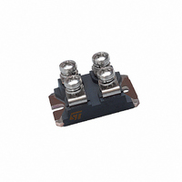
Page 6
... BYT230PIV-400 / BYT231PIV-400 PACKAGE MECHANICAL DATA ISOTOP Ordering type Marking BYT230PIV-400 BYT230PIV-400 BYT231PIV-400 BYT231PIV-400 Cooling method: by conduction (C) n Recommended torque value : 1.3 N.m (MAX 1.5 N.m) for the screws screws recom- n mended for mounting the package on the heatsink and the 4 screws given with the screw version).The screws supplied with the package are adapted for mounting on a board (or other types of terminals) with a thickness of 0 ...