HSDL-9100-021 Avago Technologies US Inc., HSDL-9100-021 Datasheet
HSDL-9100-021
Specifications of HSDL-9100-021
Available stocks


Related parts for HSDL-9100-021


HSDL-9100-021 Summary of contents
Page 1
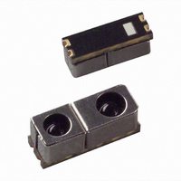
... HSDL-9100 Proximity Sensor. You can contact them through your local sales representatives for additional details. Order Information Part Number Description HSDL-9100-021 2.7mm Height HSDL-9100-024 2.4mm Height Features x Excellent optical isolation resulting in near zero optical cross-talk x High effi ...
Page 2
... Block Layout LED 1 LED_A 2 LED_K TOP VIEW Figure 1. Block Layout of HSDL-9100 Absolute Maximum Ratings (Ta=25°C) Parameter Emitter Continuous Forward Current Coupled Total Power Dissipation (refer to Figure 1) Operating Temperature Storage Temperature Reflow Soldering Temperature Electrical-Optical Characteristics (Ta=25°C) Parameter Emitter Forward Voltage ...
Page 3
... Dark Current Test Condition (Ta=25°C) LIGHT SEALED DARK BOX D LED I F Figure 3. Test Condition used are I LED 5mm INPUT OUTPUT SCOPE T R HSDL-9100 Typical Photodiode Angular Responsivity Profile -90 -80 -70 -60 -50 -40 -30 -20 - PHOTODIODE I DARK = 300mA Pulse, 5% Duty Cycle 90% 10 1.1 1.0 0.9 0.8 0.7 ...
Page 4
Typical Characteristics LED Forward Current Vs Temperature 100 Temperature (˚C) LED Forward Current Vs Forward Voltage @ Across Temperature 0.12 25 -25 0.1 85 ...
Page 5
Dark Current Vdet = 3/6/9V vs Across Temperature -40 - Temperature (˚C) Output Voltage Vs Edge Distance @ Room Temp and RL=100K Ohm ILED=300mA, D=3/4/5mm 1000 900 800 700 600 500 400 300 ...
Page 6
... HSDL-9100 Package Outlines Tx 0.10 0.05 2.35 Photodiode direction mark Figure 5a. HSDL-9100-021 Package dimensions Tx 0.1 0.05 2.35 Photodiode direction mark Figure 5b. HSDL-9100-024 Package dimensions 6 3.88 Mounting Centre 2.48 3.55 Rx 6.9 7. 3.88 Mounting Centre 2.48 3.55 Rx 6.9 7. 0.10 0.05 Pin 1 - LED Anode Pin 2 - LED Cathode ...
Page 7
... HSDL-9100-021/024 Tape and Reel Dimensions 0.35 2.78±0.07 EMPTY PARTS MOUNTED (40 mm MIN.) LABEL Figure 6. Tape and Reel Dimensions 7 1.5 1.55±0.05 2±0.1 4±0.1 8±0.1 A 2.95±0.1 PROGRESSIVE DIRECTION LEADER (400 mm MIN.) EMPTY (40 mm MIN.) OPTION # "B" "C" 001 178 60 021 ...
Page 8
... HSDL-9100 Moisture Proof Packaging All HSDL-9100 options are shipped in moisture proof package. Once opened, moisture absorption begins. This part is compliant to JEDEC Level 3. Baking Conditions If the parts are not stored in dry conditions, they must be baked before reflow to prevent damage to the parts. Package ...
Page 9
Recommended Reflow Profile 255 230 217 200 180 150 R1 120 HEAT UP Process Zone Heat Up Solder Paste Dry Solder Reflow Cool Down Time maintained above liquidus point , 217°C Peak Temperature Time within ...
Page 10
... Appendix A: HSDL-9100 SMT Assembly Application Note Recommended Metal solder Stencil Aperture It is recommended that only a 0.152 mm (0.006 inch 0.127 mm (0.005 inch) thick stencil be used for solder paste printing. This is to ensure adequate printed solder paste volume and no shorting. See Table 1 below the drawing for combinations of metal stencil aperture and metal stencil thickness that should be used ...
Page 11
... Figure 14. Mobile Application Platform 11 Interface to the Recommended I/O chip The HSDL-9100 is general interface with the GPIO pin of the controller chipset. The LED_A, pin1 is connected to the PWM port alternatively the external timer circuitry can be used to drive the LED. The DET_K, pin 4 is interface to the signal conditioning before driving the GPIO port ...
Page 12
... The next section discusses interfacing configuration with general processor including the recommended signal conditional circuitry. The DET_A pin of HSDL-9100 is connected to the filter circuit then to the comparator before interfacing with the GPIO pin. The filter circuit is implement to provide the ambient light filter. The PWM is pulse to drive the LED_K pin alternative the external timer 555 can also be replaced ...
Page 13
... Appendix C: Recommended window and light guide for HSDL-9100 Some constraints on the design and position of the win- dow are required so that the cross talk from the emitter to the photodiode is minimized. Four recommendations of window design are suggested as below: x Put the optical sensor close to the window material. ...