11599112602 C&K Components, 11599112602 Datasheet - Page 4
11599112602
Manufacturer Part Number
11599112602
Description
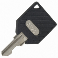
KEY REPLACEMENT A126 CODE BLACK
Manufacturer
C&K Components
Type
Keyr
Specifications of 11599112602
Accessory Type
Key Replacement
Color
Black
Illumination
Not Illuminated
Switch Type
Key Lock Switch
For Use With/related Products
P Series, Snap-In Version
For Use With
CKC8015 - SWITCH KEYLOCK SNAP-IN DPDT BLKCKC8014 - SWITCH KEYLOCK SNAP-IN SPDT BLKCKC8013 - SWITCH KEYLOCK SNAP-IN DPDT BLKCKC8012 - SWITCH KEYLOCK SNAP-IN SPDT BLK
Lead Free Status / RoHS Status
Lead free / RoHS Compliant
Other names
*11599112602
11599112602
CKC8029
Q989929
11599112602
CKC8029
Q989929


L
H Series
4 & 6 Tumbler Power Switchlocks
1
2
Nut part number: 175050700
N
CONTACTS & TERMINALS: Copper, with gold plate over nickel plate.
CONTACTS & TERMINALS: Copper, silver plated.
OPTION
CODE
Q
B
WITH NUT
COMPLIANT *
RoHS
YES
YES
COMPATIBLE *
0.468 +.062
RoHS
MOUNTING/LOCK STYLE
YES
YES
-.000
CONTACT MATERIAL
0.225
± 0.010
Clip part number: 906B00000
D
TERMINAL MATERIAL
CONTACT AND
WITH CLIP
0.034
90
0.100
SILVER
GOLD
0
0.062
Switch and Lock Assembly Instructions
0.062
0.688
1
2
0.965
± 0.010
R 0.688
0.085
* Note: See Technical Data section of this catalog for RoHS compliant and compatible
definition and specifications.
All models
1. Place lock assembly in mounting hole on panel,
2. Align keying tab on switch assembly with keying slot
3. Snap assemblies together.
4. Switch installation is permanent. Switch cannot be
LOW LEVEL/DRY CIRCUIT
0.563
0.327
0.500
secure with mounting nut.
on lock assembly.
removed from lock after assembly. Attempting to separate
switch and lock may cause damage to switchlock.
L–42
± .003
R 0.048
POWER
0.235
1.000
o
± .010
with all options when ordered with ‘Q’ contact material.
0.470
Ø 0.136
R 0.030 ± .010
0.657
0.652
BURR SIDE UP
GRAIN
DIRECTION
R 0.375
12 AMPS @ 125 V AC; 6 AMPS @ 250 V AC;
1 AMP @ 125 V DC (UL/CSA).
0.105
0.4 VA MAX. @ 20 V AC or DC MAX.
± .010
RATING
Specifications and dimensions subject to change
MOUNTING
STYLES
D
N
www.ck-components.com
PANEL MOUNTING
Dimensions are shown: Inch (mm)
.065-.085 (1,65-2,16)
PANEL THICKNESS
.195 (4,95) max.
Related parts for 11599112602
Image
Part Number
Description
Manufacturer
Datasheet
Request
R


Part Number:
Description:
Rotary Switches 4P 3 POS ROTARY SW
Manufacturer:
C&K Components
Part Number:
Description:
ANALOG ROCKER C&K DELTATECH
Manufacturer:
C&K Components
Part Number:
Description:
QUARDANT MODUL C&K DELTATECH
Manufacturer:
C&K Components
Datasheet:
Part Number:
Description:
TOGGLE,THT-PC,SPDT,ON-OFF-ON,ACT-DXL:6.09X17.15MM,BUSH-THREADED,AU
Manufacturer:
C&K Components
Part Number:
Description:
SMARTCARD CONNECTOR *Y1112-2013AP LFT
Manufacturer:
C&K Components
Part Number:
Description:
Connector reel; SIM card; 6 contacts; hinged; no switch lock
Manufacturer:
C&K Components