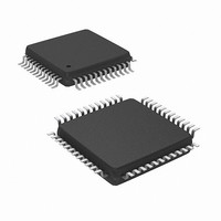
NUC100LC1BN Nuvoton Technology Corporation of America, NUC100LC1BN Datasheet - Page 220

NUC100LC1BN
Manufacturer Part Number
NUC100LC1BN
Description
IC MCU 32BIT 32KB FLASH 48LQFP
Manufacturer
Nuvoton Technology Corporation of America
Series
NuMicro™r
Specifications of NUC100LC1BN
Core Processor
ARM Cortex-M0
Core Size
32-Bit
Speed
50MHz
Connectivity
I²C, IrDA, SPI, UART/USART
Peripherals
Brown-out Detect/Reset, DMA, I²S, LVD, POR, PS2, PWM, WDT
Number Of I /o
35
Program Memory Size
32KB (32K x 8)
Program Memory Type
FLASH
Ram Size
4K x 8
Voltage - Supply (vcc/vdd)
2.5 V ~ 5.5 V
Data Converters
A/D 8x12b
Oscillator Type
Internal
Operating Temperature
-40°C ~ 85°C
Package / Case
48-LQFP
Lead Free Status / RoHS Status
Lead free / RoHS Compliant
Eeprom Size
-
Available stocks
Company
Part Number
Manufacturer
Quantity
Price
Company:
Part Number:
NUC100LC1BN
Manufacturer:
NuvoTon
Quantity:
1 600
Company:
Part Number:
NUC100LC1BN
Manufacturer:
Nuvoton Technology Corporation of America
Quantity:
10 000
Part Number:
NUC100LC1BN
Manufacturer:
NUVOTON
Quantity:
20 000
- NUC100LC1BN PDF datasheet
- NUC100LC1BN PDF datasheet #2
- NUC100LC1BN PDF datasheet #3
- NUC100LC1BN_PRODUCT_CHANGE PDF datasheet #4
- Current page: 220 of 600
- Download datasheet (6Mb)
NuMicro™ NUC100 Series Technical Reference Manual
5.4.4.8
Handling Transactions with USB Device Peripheral
User can use interrupt or polling USB_INTSTS to monitor the USB Transactions, when
transactions occur, USB_INTSTS will be set by hardware and send an interrupt request to CPU (if
related interrupt enabled), or user can polling USB_INTSTS to get these events without interrupt.
The following is the control flow with interrupt enable.
When USB host has requested data from device controller, users need to prepare related data
into the specified endpoint buffer in advance. After buffering the required data, users need to write
the actual data length in the specified MAXPLD register. Once this register is written, the internal
signal “In_Rdy” will be asserted and the buffering data will be transmitted immediately after
receiving associated IN token from Host. Note that after transferring the specified data, the signal
“In_Rdy” will de-assert automatically by hardware.
Figure 5-12 Setup Transaction followed by Data in Transaction
Alternatively, when USB host wants to transmit data to the OUT endpoint in the device controller,
hardware will buffer these data to the specified endpoint buffer. After this transaction is
completed, hardware will record the data length in related MAXPLD register and de-assert the
signal “Out_Rdy”. This will avoid hardware accepting next transaction until users move out current
data in the related endpoint buffer. Once users have processed this transaction, the related
register “MAXPLD” needs to be written by firmware to assert the signal “Out_Rdy” again to accept
next transaction.
Figure 5-13 Data Out Transfer
Publication Release Date: Dec. 22, 2010
- 220 -
Revision V1.06
Related parts for NUC100LC1BN
Image
Part Number
Description
Manufacturer
Datasheet
Request
R

Part Number:
Description:
Manufacturer:
Nuvoton Technology Corporation of America
Datasheet:

Part Number:
Description:
Manufacturer:
Nuvoton Technology Corporation of America
Datasheet:

Part Number:
Description:
Manufacturer:
Nuvoton Technology Corporation of America
Datasheet:

Part Number:
Description:
Manufacturer:
Nuvoton Technology Corporation of America
Datasheet:

Part Number:
Description:
Manufacturer:
Nuvoton Technology Corporation of America
Datasheet:

Part Number:
Description:
Manufacturer:
Nuvoton Technology Corporation of America
Datasheet:

Part Number:
Description:
Manufacturer:
Nuvoton Technology Corporation of America
Datasheet:


