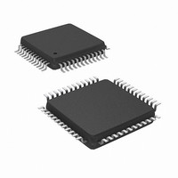
NUC100LC1BN Nuvoton Technology Corporation of America, NUC100LC1BN Datasheet - Page 262

NUC100LC1BN
Manufacturer Part Number
NUC100LC1BN
Description
IC MCU 32BIT 32KB FLASH 48LQFP
Manufacturer
Nuvoton Technology Corporation of America
Series
NuMicro™r
Specifications of NUC100LC1BN
Core Processor
ARM Cortex-M0
Core Size
32-Bit
Speed
50MHz
Connectivity
I²C, IrDA, SPI, UART/USART
Peripherals
Brown-out Detect/Reset, DMA, I²S, LVD, POR, PS2, PWM, WDT
Number Of I /o
35
Program Memory Size
32KB (32K x 8)
Program Memory Type
FLASH
Ram Size
4K x 8
Voltage - Supply (vcc/vdd)
2.5 V ~ 5.5 V
Data Converters
A/D 8x12b
Oscillator Type
Internal
Operating Temperature
-40°C ~ 85°C
Package / Case
48-LQFP
Lead Free Status / RoHS Status
Lead free / RoHS Compliant
Eeprom Size
-
Available stocks
Company
Part Number
Manufacturer
Quantity
Price
Company:
Part Number:
NUC100LC1BN
Manufacturer:
NuvoTon
Quantity:
1 600
Company:
Part Number:
NUC100LC1BN
Manufacturer:
Nuvoton Technology Corporation of America
Quantity:
10 000
Part Number:
NUC100LC1BN
Manufacturer:
NUVOTON
Quantity:
20 000
- NUC100LC1BN PDF datasheet
- NUC100LC1BN PDF datasheet #2
- NUC100LC1BN PDF datasheet #3
- NUC100LC1BN_PRODUCT_CHANGE PDF datasheet #4
- Current page: 262 of 600
- Download datasheet (6Mb)
5.6.3.3
5.6.3.4
5.6.3.5
When the bus is free/idle, meaning no master device is engaging the bus (both SCL and SDA
lines are high), a master can initiate a transfer by sending a START signal. A START signal,
usually referred to as the S-bit, is defined as a HIGH to LOW transition on the SDA line while SCL
is HIGH. The START signal denotes the beginning of a new data transfer.
A Repeated START (Sr) is no STOP signal between two START signals. The master uses this
method to communicate with another slave or the same slave in a different transfer direction (e.g.
from writing to a device to reading from a device) without releasing the bus.
STOP signal
The master can terminate the communication by generating a STOP signal. A STOP signal,
usually referred to as the P-bit, is defined as a LOW to HIGH transition on the SDA line while SCL
is HIGH.
The first byte of data transferred by the master immediately after the START signal is the slave
address. This is a 7-bits calling address followed by a RW bit. The RW bit signals the slave the
data transfer direction. No two slaves in the system can have the same address. Only the slave
with an address that matches the one transmitted by the master will respond by returning an
acknowledge bit by pulling the SDA low at the 9th SCL clock cycle.
Once successful slave addressing has been achieved, the data transfer can proceed on a byte-
by-byte basis in the direction specified by the RW bit sent by the master. Each transferred byte is
followed by an acknowledge bit on the 9th SCL clock cycle. If the slave signals a Not
Acknowledge (NACK), the master can generate a STOP signal to abort the data transfer or
generate a Repeated START signal and start a new transfer cycle.
If the master, as the receiving device, does Not Acknowledge (NACK) the slave, the slave
releases the SDA line for the master to generate a STOP or Repeated START signal.
START or Repeated START signal
Slave Address Transfer
Data Transfer
NuMicro™ NUC100 Series Technical Reference Manual
Figure 5-21 START and STOP condition
- 262 -
Publication Release Date: Dec. 22, 2010
Revision V1.06
Related parts for NUC100LC1BN
Image
Part Number
Description
Manufacturer
Datasheet
Request
R

Part Number:
Description:
Manufacturer:
Nuvoton Technology Corporation of America
Datasheet:

Part Number:
Description:
Manufacturer:
Nuvoton Technology Corporation of America
Datasheet:

Part Number:
Description:
Manufacturer:
Nuvoton Technology Corporation of America
Datasheet:

Part Number:
Description:
Manufacturer:
Nuvoton Technology Corporation of America
Datasheet:

Part Number:
Description:
Manufacturer:
Nuvoton Technology Corporation of America
Datasheet:

Part Number:
Description:
Manufacturer:
Nuvoton Technology Corporation of America
Datasheet:

Part Number:
Description:
Manufacturer:
Nuvoton Technology Corporation of America
Datasheet:


