NUC100LC1BN Nuvoton Technology Corporation of America, NUC100LC1BN Datasheet - Page 353
NUC100LC1BN
Manufacturer Part Number
NUC100LC1BN
Description
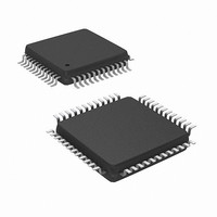
IC MCU 32BIT 32KB FLASH 48LQFP
Manufacturer
Nuvoton Technology Corporation of America
Series
NuMicro™r
Specifications of NUC100LC1BN
Core Processor
ARM Cortex-M0
Core Size
32-Bit
Speed
50MHz
Connectivity
I²C, IrDA, SPI, UART/USART
Peripherals
Brown-out Detect/Reset, DMA, I²S, LVD, POR, PS2, PWM, WDT
Number Of I /o
35
Program Memory Size
32KB (32K x 8)
Program Memory Type
FLASH
Ram Size
4K x 8
Voltage - Supply (vcc/vdd)
2.5 V ~ 5.5 V
Data Converters
A/D 8x12b
Oscillator Type
Internal
Operating Temperature
-40°C ~ 85°C
Package / Case
48-LQFP
Lead Free Status / RoHS Status
Lead free / RoHS Compliant
Eeprom Size
-
Available stocks
Company
Part Number
Manufacturer
Quantity
Price
Company:

Part Number:
NUC100LC1BN
Manufacturer:
NuvoTon
Quantity:
1 600
Company:
Part Number:
NUC100LC1BN
Manufacturer:
Nuvoton Technology Corporation of America
Quantity:
10 000
Part Number:
NUC100LC1BN
Manufacturer:
NUVOTON
Quantity:
20 000


5.9.6
Example 1, SPI controller is set as a master to access an off-chip slave device with following
specifications:
Basically, the specification of the connected off-chip slave device should be referred in details
before the following steps:
1.
2.
3.
4.
5.
6.
7.
8.
9.
Programming Examples
Data bit is latched on positive edge of serial clock
Data bit is driven on negative edge of serial clock
Data is transferred from MSB first
SPICLK is idle at low state
Only one byte of data to be transmitted/received in a transaction
Slave select signal is active low
Set the DIVIDER (SPI_DIVIDER[15:0]) register to determine the output frequency of serial
clock.
Write the SPI_SSR register a proper value for the related settings of master mode, in this
case, for example, to disable the Automatic Slave Select bit AUTOSS (SPI_SSR[3] = 0),
select low level trigger output of slave select signal in the Slave Select Active Level bit
SS_LVL (SPI_SSR[2] = 0), and select which slave select signal will be output at the IO pin
by setting the respective Slave Select Register bits SSR[0] or SSR[1] (SPI_SSR[1:0]) to
active the off-chip slave devices.
Write the related settings into the SPI_CNTRL register to control this SPI master actions,
set this SPI controller as master device in SLAVE bit (SPI_CNTRL[18] = 0), force the serial
clock idle state at low in CLKP bit (SPI_CNTRL[11] = 0), select data transmitted at negative
edge of serial clock in TX_NEG bit (SPI_CNTRL[2] = 1), select data latched at positive
edge of serial clock in RX_NEG bit (SPI_CNTRL[1] = 0), set the bit length of word transfer
as 8 bits in TX_BIT_LEN bit field (SPI_CNTRL[7:3] = 0x08), set only one time of word
transaction in TX_NUM (SPI_CNTRL[9:8] = 0x0), set MSB transfer first in LSB bit
(SPI_CNTRL[10] = 0), and don’t care the SP_CYCLE bit field (SPI_CNTRL[15:12]) due to
not burst mode in this case.
If this SPI master will transmits (writes) one byte data to the off-chip slave device, write the
byte data that will be transmitted into the TX0[7:0] (SPI_TX0[7:0]) register.
If this SPI master just only receives (reads) one byte data from the off-chip slave device,
you don’t need to care what data will be transmitted and just write 0xFF into the
SPI_TX0[7:0] register.
Enable the GO_BUSY bit (SPI_CNTRL[0] = 1) to start the data transfer at the SPI interface.
Waiting for SPI interrupt occurred (if the Interrupt Enable IE bit is set) or just polling the
GO_BUSY bit till it be cleared to 0 by hardware automatically.
Read out the received one byte data from RX0[7:0] (SPI_RX0[7:0]) register.
Go to 4) to continue another data transfer or set SSR[0] or SSR[1] to 0 to inactivate the off-
chip slave devices.
NuMicro™ NUC100 Series Technical Reference Manual
- 353 -
Publication Release Date: Oct 22, 2010
Revision V1.06
Related parts for NUC100LC1BN
Image
Part Number
Description
Manufacturer
Datasheet
Request
R

Part Number:
Description:
Manufacturer:
Nuvoton Technology Corporation of America
Datasheet:
Part Number:
Description:
Manufacturer:
Nuvoton Technology Corporation of America
Datasheet:
Part Number:
Description:
Manufacturer:
Nuvoton Technology Corporation of America
Datasheet:
Part Number:
Description:
Manufacturer:
Nuvoton Technology Corporation of America
Datasheet:
Part Number:
Description:
Manufacturer:
Nuvoton Technology Corporation of America
Datasheet:
Part Number:
Description:
Manufacturer:
Nuvoton Technology Corporation of America
Datasheet:
Part Number:
Description:
Manufacturer:
Nuvoton Technology Corporation of America
Datasheet: