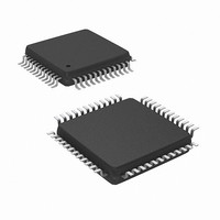
NUC100LC1BN Nuvoton Technology Corporation of America, NUC100LC1BN Datasheet - Page 491

NUC100LC1BN
Manufacturer Part Number
NUC100LC1BN
Description
IC MCU 32BIT 32KB FLASH 48LQFP
Manufacturer
Nuvoton Technology Corporation of America
Series
NuMicro™r
Specifications of NUC100LC1BN
Core Processor
ARM Cortex-M0
Core Size
32-Bit
Speed
50MHz
Connectivity
I²C, IrDA, SPI, UART/USART
Peripherals
Brown-out Detect/Reset, DMA, I²S, LVD, POR, PS2, PWM, WDT
Number Of I /o
35
Program Memory Size
32KB (32K x 8)
Program Memory Type
FLASH
Ram Size
4K x 8
Voltage - Supply (vcc/vdd)
2.5 V ~ 5.5 V
Data Converters
A/D 8x12b
Oscillator Type
Internal
Operating Temperature
-40°C ~ 85°C
Package / Case
48-LQFP
Lead Free Status / RoHS Status
Lead free / RoHS Compliant
Eeprom Size
-
Available stocks
Company
Part Number
Manufacturer
Quantity
Price
Company:
Part Number:
NUC100LC1BN
Manufacturer:
NuvoTon
Quantity:
1 600
Company:
Part Number:
NUC100LC1BN
Manufacturer:
Nuvoton Technology Corporation of America
Quantity:
10 000
Part Number:
NUC100LC1BN
Manufacturer:
NUVOTON
Quantity:
20 000
- NUC100LC1BN PDF datasheet
- NUC100LC1BN PDF datasheet #2
- NUC100LC1BN PDF datasheet #3
- NUC100LC1BN_PRODUCT_CHANGE PDF datasheet #4
- Current page: 491 of 600
- Download datasheet (6Mb)
5.16.4.6 Input Sampling and A/D Conversion Time
5.16.4.7 Conversion Result Monitor by Compare Mode
A/D conversion can be triggered by external pin request. When the ADCR.TRGEN is set to high
to enable ADC external trigger function, setting the TRGS[1:0] bits to 00b is to select external
trigger input from the STADC pin. Software can set TRGCOND[1:0] to select trigger condition is
falling/rising edge or low/high level. An 8-bit sampling counter is used to deglitch. If level trigger
condition is selected, the STADC pin must be kept at defined state at least 8 PCLKs. The ADST
bit will be set to 1 at the 9th PCLK and start to conversion. Conversion is continuous if external
trigger input is pull at low (or high state) in level trigger mode. It is stopped only when external
condition trigger condition disappears. If edge trigger condition is selected, the high and low state
must be kept at least 4 PLCKs. Pulse that is shorter than this specification will be ignored.
ADC external trigger function is only supported at single-cycle scan mode.
ADC controller provide two sets of compare register ADCMPR0 and 1 to monitor maximum two
specified channels conversion result from A/D conversion controller, refer to Figure 5-100.
Software can select which channel to be monitored by set CMPCH(ADCMPRx[5:0]) and
CMPCOND bit is used to check conversion result is less than specify value or greater than (equal
to) value specified in CMPD[11:0]. When the conversion of the channel specified by CMPCH is
completed, the comparing action will be triggered one time automatically. When the compare
result meets the setting, compare match counter will increase 1, otherwise, the compare match
counter will be clear to 0. When counter value reach the setting of (CMPMATCNT+1) then CMPF
bit will be set to 1, if CMPIE bit is set then an ADC_INT interrupt request is generated. Software
can use it to monitor the external analog input pin voltage transition in scan mode without
imposing a load on software. Detail logics diagram is shown as below:
NuMicro™ NUC100 Series Technical Reference Manual
Figure 5-100 A/D Conversion Result Monitor Logics Diagram
- 491 -
Publication Release Date: Oct 22, 2010
Revision V1.06
Related parts for NUC100LC1BN
Image
Part Number
Description
Manufacturer
Datasheet
Request
R

Part Number:
Description:
Manufacturer:
Nuvoton Technology Corporation of America
Datasheet:

Part Number:
Description:
Manufacturer:
Nuvoton Technology Corporation of America
Datasheet:

Part Number:
Description:
Manufacturer:
Nuvoton Technology Corporation of America
Datasheet:

Part Number:
Description:
Manufacturer:
Nuvoton Technology Corporation of America
Datasheet:

Part Number:
Description:
Manufacturer:
Nuvoton Technology Corporation of America
Datasheet:

Part Number:
Description:
Manufacturer:
Nuvoton Technology Corporation of America
Datasheet:

Part Number:
Description:
Manufacturer:
Nuvoton Technology Corporation of America
Datasheet:


