EA EDIPTFT43-ATP ELECTRONIC ASSEMBLY, EA EDIPTFT43-ATP Datasheet - Page 6
EA EDIPTFT43-ATP
Manufacturer Part Number
EA EDIPTFT43-ATP
Description
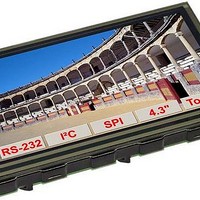
TFT Displays & Accessories 4.3 TFT w/ Touch w/ Intellegence
Manufacturer
ELECTRONIC ASSEMBLY
Datasheet
1.EA_EDIPTFT43-A.pdf
(28 pages)
Specifications of EA EDIPTFT43-ATP
Background Color
White
Interface Type
RS-232, I2C, SPI-Bus
Maximum Operating Temperature
+ 70 C
Minimum Operating Temperature
- 20 C
Operating Current
180 mA
Product
Displays
Supply Voltage
5 V
Touch Panel
Touch Panel
Pixel Density
480 x 272
Module Size (w X H X T)
107 mm x 71 mm x 12 mm
Backlighting
LED
Lead Free Status / RoHS Status
Lead free / RoHS Compliant


EA eDIPTFT43-A
Page 6
SPI INTERFACE
If the display is wired as shown
below, SPI mode is activated.
The data is then transferred via
the serial, synchronous SPI
interface.
The transfer parameter will be
set via the pins DORD, CPOL
and CPHA.
Note:
The pins DORD, CPOL, CPHA, DPOM, DPROT and TEST/SBUF have an internal pullup, which is why only the LO level
(0=GND) is to be actively applied. These pins must be left open for a Hi level.
On pin 20 (SBUF) the display indicates with a low level that data is ready to be retrieved from the internal send buffer.
The line can be connected to an interrupt input of the host system, for example.
DATA TRANSFER SPI
Write operation: a clock rate up to 200 kHz is allowed
without any stop. Together with a pause of 100 µs
between every data byte a clock rate up to 3 MHz can
be reached.
Read operation: to read data (e.g. the "ACK" byte) a
dummy byte (e.g . 0xFF) need to be sent.
Note that the EA eDIP for internal operation does need
a short time before providing the data; therefore a short
pause of min. 6µs (no activity of CLK line) is needed for
each byte.
Pin Symbol In/Out Function
10
11 SPIMO
12
13 DPOM
14
15
16
17 DPROT
18
19
20
1
2
3
4
5
6
7
8
9
application example
RESET
DORD
CPOL
CPHA
SBUF
MOSI
MISO
BUZZ
TEST
GND
VDD
DNC
CLK
WP
NC
NC
SS
NC
Out
Out
Out
Out
IN
In
In
In
In
In
In
In
In
In
In
In
Ground Potential for logic (0V)
Power supply for logic (+5V)
do not connect
do not connect
L: Reset
Slave Select
Serial In
Serial Out
Shift Clock
Data Order (0=MSB first; 1=LSB first)
connect to GND for SPI interface
do not connect
L: disable PowerOnMacro
do not connect for normal operation
Clock Polarity (0=LO 1=HI when idle)
Clock Phase sample 0=1st;1=2nd edge
Buzzer output
L: Disable Smallprotokoll
do not connect for normal operation
L: internal, do not connect
L: Writeprotect for DataFlash
open-drain with internal pullup 20..50k
IN (Power-On) L: Testmode
OUT L: data in sendbuffer
Pinout eDIPTFT43-A: SPI mode
Pin
21
22
23
24
25
26
27
28
29
30
31
32
33
34
35
36
37
38
39
40
OUT1 / MO8
OUT2 / MO7
OUT3 / MO6
OUT4 / MO5
OUT5 / MO4
OUT6 / MO3
OUT7 / MO2
OUT8 / MO1
IN1 / MI8
IN2 / MI7
IN3 / MI6
IN4 / MI5
IN5 / MI4
IN6 / MI3
IN7 / MI2
IN8 / MI1
Symbol
AIN1
AIN2
GND
VDD
ELECTRONIC ASSEMBLY reserves
the right to change specifications
without prior notice. Printing and
typographical
In/Out Function
Out
In
In
Ground (0V)
Power supply (+5V)
analogue input 0..5V
DC impedance 1MOhm
8 digital outputs
maximum current:
IOL = IOH = 10mA
alternativ up to 8 matrix
keyboard output lines
(reduces the digital
output lines, see chapter
external keyboard)
8 digital inputs
open-drain with internal
pullup 20..50k
alternativ up to 8 matrix
keyboard input lines
(reduces the digital input
lines, see chapter
external keyboard)
errors
reserved.
Related parts for EA EDIPTFT43-ATP
Image
Part Number
Description
Manufacturer
Datasheet
Request
R

Part Number:
Description:
Display Development Tools StrEval Kit Blk-Wht w/ Intf Exp and CD
Manufacturer:
ELECTRONIC ASSEMBLY
Datasheet:

Part Number:
Description:
Display Modules & Development Tools Starter/Demoboard Windows USB For DOGM
Manufacturer:
ELECTRONIC ASSEMBLY

Part Number:
Description:
Display Modules & Development Tools Starter/Demoboard DOGM/ Windows USB
Manufacturer:
ELECTRONIC ASSEMBLY
Datasheet:

Part Number:
Description:
LCD Character Display Modules 4x20 Yellow/Green RS-232 Interface
Manufacturer:
ELECTRONIC ASSEMBLY
Part Number:
Description:
LCD Character Display Modules 4x20 Blue-White RS-232 Interface
Manufacturer:
ELECTRONIC ASSEMBLY
Part Number:
Description:
LCD Character Display Modules 2x16 Yellow/Green RS-232 Interface
Manufacturer:
ELECTRONIC ASSEMBLY

Part Number:
Description:
LCD Character Display Modules STN(+) Reflective Yel/Grn Background
Manufacturer:
ELECTRONIC ASSEMBLY
Datasheet:

Part Number:
Description:
LCD Character Display Modules STN(-) Transmissive Blue Background
Manufacturer:
ELECTRONIC ASSEMBLY
Datasheet:

Part Number:
Description:
LCD Character Display Modules FSTN(-) Transmissive Black Background
Manufacturer:
ELECTRONIC ASSEMBLY
Datasheet:
Part Number:
Description:
LCD Character Display Modules Yel/Green Contrast Yl/Grn LED Backlight
Manufacturer:
ELECTRONIC ASSEMBLY
Datasheet:

Part Number:
Description:
LCD Touch Panels Touchpanel Analog for DOGM128-6
Manufacturer:
ELECTRONIC ASSEMBLY
Datasheet:
Part Number:
Description:
LCD Touch Panels Touchpanel Analog For DOGS102
Manufacturer:
ELECTRONIC ASSEMBLY
Datasheet:
Part Number:
Description:
LCD Touch Panels Touchpanel Analog For DOGXL160
Manufacturer:
ELECTRONIC ASSEMBLY
Datasheet:
Part Number:
Description:
LCD Touch Panels Touchpanel Analog For DOG-L128-6
Manufacturer:
ELECTRONIC ASSEMBLY
Datasheet:

Part Number:
Description:
LED Displays Bezel 017-xx Series 75.0x24.2/ 91.0x36.4
Manufacturer:
ELECTRONIC ASSEMBLY
Datasheet: