VNC2 DEBUG MODULE FTDI, VNC2 DEBUG MODULE Datasheet
VNC2 DEBUG MODULE
Specifications of VNC2 DEBUG MODULE


Related parts for VNC2 DEBUG MODULE


VNC2 DEBUG MODULE Summary of contents
Page 1
... Future Technology Devices International Ltd. VNC2 Debug Module Future Technology Devices International Ltd (FTDI) Unit 1, 2 Seaward Place, Centurion Business Park, Glasgow, G41 1HH, United Kingdom Tel.: +44 (0) 141 429 2777 E-Mail (Support): Neither the whole nor any part of the information contained in, or the product described in this manual, may be adapted or reproduced in any material or electronic form without the prior written consent of the copyright holder ...
Page 2
... Vinculum-II IDE development software and the debug interface pin on the FTDI Vinculum-II (VNC2) USB host controller device. The VNC2 debug module consists of a miniature board with a USB miniB connector, which provides USB connectivity to Vinculum-II IDE development tools running on a PC. The VNC2 debug module can be used to program and debug firmware running on the VNC2 device ...
Page 3
... Debug Module Schematic Diagram .................................................... 12 7 Contact Information............................................................................. 13 Appendix A – List of Figures and Tables ................................................................... 14 List of Figures............................................................................................................... 14 List of Tables ................................................................................................................ 14 Appendix B – Revision History ................................................................................... 15 Copyright © 2010 Future Technology Devices International Limited VNC2 Debug Module Datasheet Version 1.0 Table of Contents Document Reference No.: FT_000254 Clearance No.: FTDI# 149 2 ...
Page 4
... UHCI/OHCI/EHCI host controller compatible. 5V Power output to V2DIP-x module (if needed). 2.2 Software Drivers USB drivers for the FT232R device, featured on the VNC2 debug module, are available from http://www.ftdichip.com. 2.3 Part Number The part number for the board is- VNC2 DEBUG MODULE Copyright © 2010 Future Technology Devices International Limited VNC2 Debug Module Datasheet Version 1 ...
Page 5
... References The following reference documents are recommended to provide additional information on the application and function of the VNC2 debug module. Document Name Description 1. FT_000138 Vinculum-II Embedded Dual USB Host Controller IC Data Sheet. 2. FT_000053 FT232R Data Sheet. 3. FT_000163 V2DIP1-32 Data Sheet. 4. FT_000164 V2DIP2-32 Data Sheet. ...
Page 6
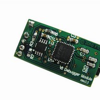
... Functional Description 3.1 Module Layout Top View Copyright © 2010 Future Technology Devices International Limited Figure 3.1 VNC2 Debug Module Layout. Document Reference No.: FT_000254 VNC2 Debug Module Datasheet Version 1.0 Clearance No.: FTDI# 149 Bottom View 5 ...
Page 7
... Table 3.2 Signal Descriptions Note: Signal levels on pins 1, 4 and 5 have 3.3V signalling levels to match the VNC2 interface. Copyright © 2010 Future Technology Devices International Limited VNC2 Debug Module Datasheet Version 1.0 Board Description Designator Debug connector, 6-way 2mm pitch female connector. ...
Page 8
... Where a customer is developing their own VNC2 based hardware, customers can support the VNC2 debug module connectivity by hosting a compatible connector on their PCB. The VNC2 debug module requires a 6-pin, 2mm pitch male connector providing connectivity to the VNC2 debug pin, PROG# and RESET# pins, as well as GND and VCC pins ...
Page 9
... Confirm Debug Connection Using IDE Having connected the VNC2 debug module to the VNC2 hardware, a user can verify the operation of the debug interface operation using the Vinculum II IDE development software. Simply connect the debug module via the mini-B USB connector. Open the Vinculum II IDE software. Under the ‘ ...
Page 10
... Typical Maximum 4.25 5.0 5. 400 -40 +85 Document Reference No.: FT_000254 VNC2 Debug Module Datasheet Version 1.0 Clearance No.: FTDI# 149 Units Conditions V Dependent upon USB port connected to the VNC2 Debug Module. mA Current supply controlled by a switch on the debug module, where the VCC supply is switched off when the device is placed in USB suspend mode ...
Page 11
... Mechanical Dimensions 5.1 Debug Module PCB Mechanical details Dimensions in mm.Tolerance is ±0.1mm 1.93mm 2.5mm Figure 5.1 VNC2 Debug Module Dimensions (Top View) 3.9mm 6.4mm Figure 5.2 VNC2 Debug Module Dimensions (Side View) Copyright © 2010 Future Technology Devices International Limited Document Reference No.: FT_000254 VNC2 Debug Module Datasheet Version 1 ...
Page 12
... Debug Connector Mechanical Details Figure 5.3 VNC2 Debug Module 6 way Female Header - Mechanical Details (n=6) Dimensions in mm. Tolerance is ±0.1mm Copyright © 2010 Future Technology Devices International Limited Document Reference No.: FT_000254 VNC2 Debug Module Datasheet Version 1.0 Clearance No.: FTDI# 149 11 ...
Page 13
... Debug Module Schematic Diagram Figure 6.1 Debug Module Schematic Diagram Copyright © 2010 Future Technology Devices International Limited Document Reference No.: FT_000254 VNC2 Debug Module Datasheet Version 1.0 Clearance No.: FTDI# 149 12 ...
Page 14
... Please visit the Sales Network page of the FTDI Web site for the contact details of our distributor(s) and sales representative(s) in your country. Copyright © 2010 Future Technology Devices International Limited Document Reference No.: FT_000254 VNC2 Debug Module Datasheet Version 1.0 Clearance No.: FTDI# 149 13 ...
Page 15
... Figure 3.4 VNC2 Connection Confirmation on Vinculum-II IDE ............................................................ 8 Figure 5.1 VNC2 Debug Module Dimensions (Top View) ................................................................... 10 Figure 5.2 VNC2 Debug Module Dimensions (Side View) .................................................................. 10 Figure 5.3 VNC2 Debug Module 6 way Female Header - Mechanical Details (n=6) ............................... 11 Figure 6.1 Debug Module Schematic Diagram ................................................................................. 12 List of Tables Table 2 ...
Page 16
... Appendix B – Revision History Version 1 Copyright © 2010 Future Technology Devices International Limited Document Reference No.: FT_000254 VNC2 Debug Module Datasheet Version 1.0 Clearance No.: FTDI# 149 th 15 April 2010 15 ...