AH114-89G TriQuint, AH114-89G Datasheet

RF Amplifier 60-2500MHz 19dB Gain@900MHz

AH114-89G

Manufacturer Part Number
AH114-89G
Description
RF Amplifier 60-2500MHz 19dB Gain@900MHz
Manufacturer
TriQuint
Type
General Purpose Amplifierr
Datasheet

Specifications of AH114-89G

Mounting Style
SMD/SMT
Number Of Channels
1
Operating Frequency
2500 MHz
Noise Figure
5 dB @ 1900 MHz
Operating Supply Voltage
5 V
Supply Current
170 mA @ 5 V
Maximum Operating Temperature
+ 220 C
Minimum Operating Temperature
- 40 C
Package / Case
SOT-89
Lead Free Status / RoHS Status
Lead free / RoHS Compliant
Other names
1066856

Available stocks

Company
Part Number
Manufacturer
Quantity
Price
Part Number:
AH114-89G
Manufacturer:
TriQuint Semiconductor
Quantity:
135
Part Number:
AH114-89G
Manufacturer:
WJ
Quantity:
20 000
Company:
Part Number:
AH114-89G
Quantity:
3
Product Features
Applications
Specifications
1. Test conditions unless otherwise noted: 25 ºC, Vsupply = +5 V, in tuned application circuit.
2. 3OIP measured with two tones at an output power of +11 dBm/tone separated by 1 MHz. The
Absolute Maximum Rating
Operation of this device above any of these parameters may cause permanent damage.
WJ Communications, Inc • Phone 1-800-WJ1-4401 • FAX: 408-577-6621 • e-mail: sales@wj.com • Web site: www.wj.com, www.TriQuint.com
Parameters
Operational Bandwidth
Test Frequency
Gain
Input Return Loss
Output Return Loss
Output P1dB
Output IP3
IS-95A Channel Power
Noise Figure
Test Frequency
Gain
Output P1dB
Output IP3
Operating Current Range
Device Voltage
Parameter
Storage Temperature
RF Input Power (continuous)
Device Voltage
Device Current
Junction Temperature
Thermal Resistance, Rth
60 – 2500 MHz
+24 dBm P1dB
+41 dBm Output IP3
19 dB Gain @ 900 MHz
14.5 dB Gain @ 1900 MHz
+5V Single Positive Supply
Lead-free / Green / RoHS-
compliant SOT-89 Package
Final stage amplifiers for
Repeaters
Mobile Infrastructure
DBS / WLL / WLAN / WiBro
Defense / Homeland Security
suppression on the largest IM3 product is used to calculate the 3OIP using a 2:1 rule.
@ -45 dBc ACPR
AH114
¼ Watt, High Linearity InGaP HBT Amplifier
(2)
(2)
(1)
Units
MHz
MHz
MHz
dBm
dBm
dBm
dBm
dBm
mA
dB
dB
dB
dB
dB
V
The AH114 is a high dynamic range driver amplifier in a
low-cost surface mount package. The InGaP/GaAs HBT is
able to achieve high performance across a broad range with
+41 dBm OIP3 and +24 dBm of compressed 1dB power. It
is housed in a lead-free/green/RoHS-compliant SOT-89
SMT package. All devices are 100% RF and DC tested.
The AH114 is targeted for use as a driver amplifier in
wireless infrastructure where high linearity and medium
power is required.
AH114 to maintain high linearity over temperature and
operate directly off a single +5V supply. This combination
makes the device an excellent candidate for transceiver line
cards in current and next generation multi-carrier 3G base
stations.
Rating
-65 to +150 °C
+15 dBm
+6 V
220 mA
+220 °C
149 °C / W
+39.5
Min
13.5
130
60
Product Description
Typ
1900
2140
14.5
+23
+41
+17
+23
+40
150
5.0
+5
10
14
14
Max
2500
An internal active bias allows the
170
Typical Performance
Ordering Information
Standard T/R size = 1000 pieces on a 7” reel.
Parameters
Frequency
S21 - Gain
S11 - Input R.L.
S22 - Output R.L.
Output P1dB
Output IP3
Noise Figure
Supply Bias
Part No.
AH114-89G
AH114-89PCB900
AH114-89PCB1900 1900 MHz Evaluation Board
AH114-89PCB2140 2140 MHz Evaluation Board
Specifications and information are subject to change without notice
Description
¼ Watt, High Linearity InGaP HBT Amplifier
(lead-free/green/RoHS-compliant SOT-89 Pkg)
900 MHz Evaluation Board
Units
MHz
dBm
dBm
dB
dB
dB
dB
Functional Diagram
Output / Collector
(1)
RF IN
Input / Base
1
+24
+40
900
Function
-14
-10
5.0
19
Ground
+5 V @ 150 mA
GND
GND
Typical
2
Page 1 of 6 January 2008
4
1900
14.5
+23
+41
-10
-14
5.0
RF OUT
3
Pin No.
2140
+23
+40
2, 4
-25
-20
6.0
14
1
3

Related parts for AH114-89G

AH114-89G Summary of contents

Page 1

... Noise Figure +39.5 +41 Supply Bias +17 5.0 2140 14 +23 +40 130 150 170 +5 Ordering Information Part No. AH114-89G AH114-89PCB900 AH114-89PCB1900 1900 MHz Evaluation Board AH114-89PCB2140 2140 MHz Evaluation Board Standard T/R size = 1000 pieces on a 7” reel. Functional Diagram GND GND RF OUT Function Pin No. ...

Page 2

... AH114 ¼ Watt, High Linearity InGaP HBT Amplifier S-Parameters (Vcc = +5 V, Icc = 150 mA °C, unmatched 50 ohm system) Gain / Maximum Stable Gain 30 DB(|S[2,1]|) * 0.5 1 1.5 2 Frequency (GHz) Notes: The gain for the unmatched device in 50 ohm system is shown as the trace in black color. For a tuned circuit for a particular frequency expected that actual gain will be higher the maximum stable gain. The maximum stable gain is shown in the dashed red line. The impedance plots are shown from 50 – ...

Page 3

... AH114 ¼ Watt, High Linearity InGaP HBT Amplifier 900 MHz Application Circuit (AH114-89PCB900) Typical RF Performance Frequency 900 MHz S21 – Gain 19 dB S11 – Input Return Loss -14 dB S22 – Output Return Loss -10 dB Output IP3 +40 dBm (+11 dBm / tone, 1 MHz spacing) ...

Page 4

... WJ Communications, Inc • Phone 1-800-WJ1-4401 • FAX: 408-577-6621 • e-mail: sales@wj.com • Web site: www.wj.com, www.TriQuint.com All passive components are of size 0603 unless otherwise noted. RES ID=R1 R=2700 Ohm L2 should be placed 19.5° @ 2.14GHz from pin 1 of the AH114. CAP CAP PORT ID=C4 ID=L2 ...

Page 5

... C=1e7 pF RES R=2700 Ohm IND L=470 nH IND RES L=18 nH PORT R=3.9 Ohm P=2 Z=50 Ohm CAP C=1000 pF SUBCKT ID=U1 NET="AH114" 130 140 DB(|S[2,2]|) 130 140 Specifications and information are subject to change without notice Page January 2008 CAP C=1000 pF CAP C=10 pF ...

Page 6

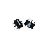
... AH114 ¼ Watt, High Linearity InGaP HBT Amplifier AH114-89G (Green / Lead-free SOT-89 Package) Mechanical Information This package is lead-free/Green/RoHS-compliant compatible with both lead-free (maximum 260 °C reflow temperature) and leaded (maximum 245 °C reflow temperature) soldering processes. The plating material on the leads is NiPdAu. ...

Related keywords