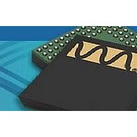
WM9090ECS/R Wolfson Microelectronics, WM9090ECS/R Datasheet - Page 32

WM9090ECS/R
Manufacturer Part Number
WM9090ECS/R
Description
Audio CODECs Audio Subsystem w/ capless headphones
Manufacturer
Wolfson Microelectronics
Specifications of WM9090ECS/R
Interface Type
2-Wire, l2C
Thd Plus Noise
80 dB
Ic Function
Ultra Low Power Audio Subsystem
Brief Features
Mono Class D Speaker Driver, Automatic Gain Control (AGC)
Supply Voltage Range
2.7V To 5.5V
Operating Temperature Range
-40°C To +85°C
Rohs Compliant
Yes
Lead Free Status / RoHS Status
Lead free / RoHS Compliant
WM9090
w
CLOCKING CONTROL
HEADPHONE OUTPUT CONFIGURATIONS
The headphone output pins HPOUTL and HPOUTR are driven by the headphone output PGAs. Each
PGA has its own dedicated volume control, as described in the “Output Signal Path” section. The
inputs to these PGAs come from the respective output mixers MIXOUTL or MIXOUTR.
The headphone output driver is capable of driving up to 35mW into a 16Ω load such as a stereo
headset or headphones. The outputs are ground-referenced, eliminating any requirement for AC
coupling capacitors. This is achieved by having separate positive and negative supply rails powered
by an on-chip charge pump. A DC Servo circuit removes any DC offset from the headphone outputs,
suppressing ‘pop’ noise and minimising power consumption. The Charge Pump and DC Servo are
described separately (see “Charge Pump” and “DC Servo” respectively).
The zobel network components should be connected to the headphone output pins HPOUTL and
HPOUTR for best audio performance in all applications. The components of the zobel network have
the effect of dampening high frequency oscillations and instabilities that can arise outside the audio
band under certain conditions. Possible sources of these instabilities include the inductive load of a
headphone coil or an active load in the form of an external line amplifier. The capacitance of lengthy
cables or PCB tracks can also lead to amplifier instability. The zobel network should comprise of a
20Ω resistor and 100nF capacitor in series with each other, as illustrated in Figure 5.
Figure 5 Zobel Network Components for HPOUTL and HPOUTR
The internal clocks for the WM9090 are derived from a common internal clock source, CLK_SYS.
This clock is the reference for the Control Write Sequencer, Class D switching amplifier, DC servo
control and other internal functions.
CLK_SYS is derived from an internal oscillator; this is controlled by the OSC_ENA register. The
frequency of CLK_SYS is nominally 6MHz; internal dividers generate the other required clocks from
this reference.
A slow clock, TOCLK, is used to set the timeout period for volume updates when zero-cross detect is
used. This clock is derived from CLK_SYS and is enabled by TOCLK_ENA. The slow clock
frequency is selected using the programmable dividers TOCLK_RATE, TOCLK_RATE_X4 and
TOCLK_RATE_DIV16. See Table 17 for a list of possible TOCLK rates.
The clocking configuration is illustrated in Figure 6. The control registers associated with WM9090
Clocking are defined in Table 16.
PD, November 2010, Rev 4.1
Production Data
32


