BAT54C-TP MCC, BAT54C-TP Datasheet
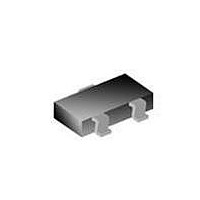
Schottky (Diodes & Rectifiers) .3A 30V

BAT54C-TP

Manufacturer Part Number
BAT54C-TP
Description
Schottky (Diodes & Rectifiers) .3A 30V
Manufacturer
MCC
Datasheet

Specifications of BAT54C-TP

Product
Schottky Diodes
Peak Reverse Voltage
30 V
Forward Continuous Current
0.2 A
Max Surge Current
0.6 A
Configuration
Dual Common Cathode
Recovery Time
5 ns
Forward Voltage Drop
1 V @ 0.1 A
Maximum Reverse Leakage Current
2 uA @ 25 V
Operating Temperature Range
- 55 C to + 125 C
Mounting Style
SMD/SMT
Package / Case
SOT-23
Lead Free Status / RoHS Status
Lead free / RoHS Compliant

Available stocks

Company
Part Number
Manufacturer
Quantity
Price
Part Number:
BAT54C-TP
Manufacturer:
MCC/美微科
Quantity:
20 000
Micro Commercial Components
Features
Revision: A
BAT54
BAT54A
BAT54C
BAT54S
Maximum Ratings
Continuos Reverse Voltage
Forward ContinuousCurrent
Non-Repetitive Peak Forward Current t<1s
Total Power Dissipation @ T
Storage Temperature Range
Operating Junction Temperature Range
Soldering temperature during 10s
Electrical Characteristics @ 25 °C Unless Otherwise Specified
Forward Voltage at
Reverse Current
Capacitance
Reverse Recovery
Time
Thermal Resistance,
Junction to Ambient
MCC Catalog
Characteristics
M C C
Low Forward Voltage
Surface Mount device
Epoxy meets UL 94 V-0 flammability rating
Moisture Sensitivity Level 1
Number
I
I
I
I
I
F
F
F
F
F
= 0.1mA
= 1mA
= 10mA
= 30mA
= 100mA
KL2
KL1
KL3
KL4
Device Marking
1
Symbol
R
V
C
I
t
A
θJA
R
rr
www.mccsemi.com
TM
F
J
= 25°C
L42
L43
L44
L4
2
  omponents
20736 Marilla Street Chatsworth

  !"#
$ %    !"#
500
1000mV
240mV
320mV
400mV
500mV
2.0 uA
10pF
Max.
5nS
°C/W
Single
Dual
Dual
Dual
Type
I
T
P
V
FSM
T
T
I
stg
F
D
R
j
Measured at
1.0MHz, V
I
I
V
F
(REC)
=I
R
R
= 25V
-55°C to 150°C
-55°C to 125°C
=10mA;
Configuration
= 1mA
See page 3
Figure 1
Figure
Figure 3
Figure 4
Notes
200mW
260°C
200mA
1 of 3
0.6A
Pin
30V
R
=1.0V
2
G
DIM
Schottky Barrier Diode
C
D
A
B
E
F
G
H
K
J
200mWatt, 30Volt
F
K
INCHES
.0005
.110
.083
.047
.035
.070
.018
.035
.003
.015
MIN
.035
.900
A
E
. 037
.950
Suggested Solder
D
BAT54S
BAT54
. 031
.800
THRU
SOT-23
.0039
MAX
.120
.098
.055
.041
.081
.024
.044
.007
.020
Pad Layout
DIMENSIONS
.950
.037
H
C
B
2.80
2.10
1.20
MIN
1.78
.013
.085
.89
.45
.89
.37
MM
.079
2.000
J
MAX
3.04
2.64
1.40
1.03
2.05
.100
1.12
.180
.60
.51
2011/01/01
in ches
mm
NOTE

Related parts for BAT54C-TP

BAT54C-TP Summary of contents

Page 1

... Surface Mount device Epoxy meets UL 94 V-0 flammability rating Moisture Sensitivity Level 1 Device Marking MCC Catalog Number 1 KL1 BAT54 BAT54A KL2 BAT54C KL3 BAT54S KL4 Maximum Ratings Continuos Reverse Voltage Forward ContinuousCurrent Non-Repetitive Peak Forward Current t<1s Total Power Dissipation @ T = 25°C A ...

Page 2

... Pin Configuration - Top View 3 2 Figure 2 BAT54A Micro Commercial Components 100 T = 125º 75º 25º 0ºC A 0.01 0.001 INSTANTANEOUS REVERSE VOLTAGE (V) R Fig. 2 Typical Reverse Characteristics 200 100 AMBIENT TEMPERATURE ( C) A Fig. 4 Power Derating Curve Figure 3 Figure 4 BAT54C BAT54S 100 125 ° 2011/01/01 ...

Page 3

... Micro Commercial Components Corp . and all the companies whose products are represented on our website, harmless against all damages. MCC's products are not authorized for use as critical components in life support devices or systems without the express written Counterfeiting of semiconductor parts is a growing problem in the industry. Micro Commercial Components (MCC) is taking strong measures to protect ourselves and our customers from the proliferation of counterfeit parts ...

Related keywords