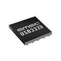
USB3300-EZK-TR SMSC, USB3300-EZK-TR Datasheet - Page 31

USB3300-EZK-TR
Manufacturer Part Number
USB3300-EZK-TR
Description
USB Interface IC USB 2.0 PHY ULPI
Manufacturer
SMSC
Type
Hi Speed USB Host Devicer
Datasheet
1.USB3300-EZK.pdf
(55 pages)
Specifications of USB3300-EZK-TR
Maximum Operating Temperature
+ 85 C
Minimum Operating Temperature
- 40 C
Mounting Style
SMD/SMT
Operating Temperature Range
- 40 C to + 85 C
Operating Supply Voltage
3.3 V
Package / Case
QFN-32
Lead Free Status / RoHS Status
Lead free / RoHS Compliant
Available stocks
Company
Part Number
Manufacturer
Quantity
Price
Company:
Part Number:
USB3300-EZK-TR
Manufacturer:
MICRON
Quantity:
3 140
Part Number:
USB3300-EZK-TR
Manufacturer:
MICROCHIP/微芯
Quantity:
20 000
Hi-Speed USB Host, Device or OTG PHY with ULPI Low Pin Interface
Datasheet
SMSC USB3300
6.1.7
DATA[7:0]
[1:0]
[3:2]
[5:4]
[6]
[7]
Notes:
1. An ‘X’ is a do not care and can be either a logic 0 or 1.
2. The value of VbusValid is defined in
USB3300 Transmitter
The USB3300 ULPI transmitter fully supports HS, FS, and LS transmit operations. Figure 6.2, "ULPI
Digital Block Diagram" shows the high speed, full speed, and low speed transmitter block controlled
by ULPI Protocol Block. Encoding of the USB packet follows the bit-stuffing and NRZI outlined in the
USB 2.0 specification. Many of these functions are re-used between the high speed and full/low speed
transmitters. When using the USB3300,
always be used as a guideline on how to configure for various modes of operation. The transmitter
decodes the inputs of Xcvrselect, Termselect, opmodes, DpPulldown and DmPulldown to determine
what operation is expected. Users must strictly adhere to the modes of operation given in
Several important functions for a device and host are designed in the transmitter blocks.
NAME
Reserved
Rx Event
Encoding
Linestate
Encoded
during a USB receive when NXT is low.
after STP is asserted during a USB transmit cmd.
State of
ID pin
Vbus
State
DESCRIPTION AND VALUE
UTMI Linestate Signals
DATA[1] = Linestate[1]
DATA[0] = Linestate[0]
ENCODED VBUS VOLTAGE STATES
ENCODED UTMI EVENT SIGNALS
Set to the logic state of the ID pin. A logic low indicates an A device. A logic high
indicates a B device.
Always
VALUE
VALUE
00
01
10
00
01
10
11
11
Table 6.5 ULPI RX CMD Encoding
V
V
V
V
V
V
VBUS
SESS_END
SESS_VLD
SESS_VLD
VBUS_VLD
VBUS_VLD
VBUS VOLTAGE
DATASHEET
< V
RXACTIVE
SESS_END
< V
< V
< V
Table 6.10, "External Vbus Indicator
0
1
1
X
Table 6.8, "DP/DM termination vs. Signaling Mode"
31
VBUS
VBUS
VBUS
<
<
RXERROR
SESSEND
X
X
X
1
0
0
0
1
SESSVLD
HOSTDISCONNECT
Logic".
X
0
0
1
Revision 1.08 (11-07-07)
0
0
0
1
VBUSVLD
Table
0
0
0
1
should
6.8.
2


