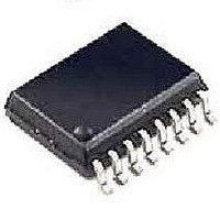
DG442DY-T1-E3 Vishay, DG442DY-T1-E3 Datasheet - Page 3

DG442DY-T1-E3
Manufacturer Part Number
DG442DY-T1-E3
Description
Analog Switch ICs Quad SPST 22/25V 18
Manufacturer
Vishay
Datasheet
1.DG441DY-T1-E3.pdf
(9 pages)
Specifications of DG442DY-T1-E3
Number Of Switches
Quad
Switch Configuration
SPST
On Resistance (max)
160 Ohms
On Time (max)
450 ns
Off Time (max)
200 ns
Off Isolation (typ)
60 dB
Supply Voltage (max)
25 V
Supply Current
0.015 mA
Maximum Power Dissipation
900 mW
Maximum Operating Temperature
+ 85 C
Mounting Style
SMD/SMT
Package / Case
SOIC-16 Narrow
Minimum Operating Temperature
- 40 C
Off State Leakage Current (max)
5 nA
Analog Switch Type
SPST
No. Of Channels
4
On State Resistance Max
50ohm
Turn Off Time
110ns
Turn On Time
150ns
Supply Voltage Range
10.8V To 13.2V
Lead Free Status / RoHS Status
Lead free / RoHS Compliant
Lead Free Status / RoHS Status
Lead free / RoHS Compliant, Lead free / RoHS Compliant
Available stocks
Company
Part Number
Manufacturer
Quantity
Price
Company:
Part Number:
DG442DY-T1-E3
Manufacturer:
FUJ
Quantity:
6 232
Document Number: 70053
S-71241–Rev. I, 25-Jun-07
SPECIFICATIONS
Parameter
Analog Switch
Analog Signal Range
Drain-Source
On-Resistance
On-Resistance Match Between
Channels
Switch Off Leakage Current
Channel On Leakage Current
Digital Control
Input Current V
Input Current V
Dynamic Characteristics
Turn-On Time
Turn-Off Time
Charge Injection
Off Isolation
Crosstalke (Channel-to-Channel)
Source Off Capacitance
Drain Off Capacitance
Channel On Capacitance
Power Supplies
Positive Supply Current
Negative Supply Current
Ground Current
e
e
IN
IN
e
Low
High
e
e
e
e
DG441
DG442
a
FOR DUAL SUPPLIES
V
Symbol
Δr
r
ANALOG
C
C
C
OIRR
X
DS(on)
I
I
I
I
t
D(off)
D(on)
DS(on)
S(off)
t
GND
OFF
D(off)
D(on)
TALK
S(off)
I
I
ON
I+
Q
IH
I-
IL
Unless Otherwise Specified
V
I
D
I
V+ = 13.5 V, V- = - 13.5 V
V+ = 16.5 V, V- = - 16.5 V
V+ = 16.5 V, V- = - 16.5 V
S
S
V+ = 16.5, V- = - 16.5 V
V+ = 15 V, V– = - 15 V
=
V
R
V
V+ = 15 V, V- = - 15 V
V
= - 10 mA, V
= - 10 mA, V
R
C
V
IN
gen
IN
L
±
V
L
Test Conditions
All Other = 2.4 V
All Other = 0.8 V
S
L
= 1 kΩ, C
V
IN
under test = 0.8 V,
= 50 Ω, C
15.5 V, V
under test = 2.4 V
V
= 1 nF, V
= V
See Figure 2
ANALOG
V
= 0 V, R
IN
= 2.4 V, 0.8 V
f = 1 MHz
f = 1 MHz
S
D
= 0 or 5 V
=
=
±
±
10 V
L
D
S
gen
=
D
L
S
15.5 V
= 35 pF
=
=
= 5 pF
0
=
=
±
= 0 Ω
±
±
V
0
8.5 V
15.5 V
10 V
V
f
Temp
Room
Room
Room
Room
Room
Room
Room
Room
Room
Room
Room
Room
Room
Room
Room
Full
Full
Full
Full
Full
Full
Full
Full
Full
Full
Full
b
- 0.0001
±
±
± 0.08
- 0.01
Typ
0.01
- 15
150
110
100
- 1
50
0.01
0.01
90
60
16
15
4
4
c
- 55 to 125 °C
Min
- 500
- 500
- 100
- 0.5
- 0.5
- 0.5
- 15
- 20
- 20
- 40
- 1
- 5
A Suffix
d
Max
100
500
500
250
120
210
100
0.5
0.5
0.5
15
85
20
20
40
4
5
Vishay Siliconix
d
DG441/442
Min
- 500
- 500
- 100
- 0.5
- 0.5
- 0.5
- 40 to 85 °C
- 15
- 10
- 5
- 5
- 1
- 5
D Suffix
d
www.vishay.com
Max
100
500
500
250
120
210
100
0.5
0.5
0.5
15
85
10
4
5
5
5
d
Unit
pC
nA
nA
pF
µA
ns
dB
Ω
V
3


