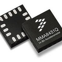
MMA8452QR1 Freescale Semiconductor, MMA8452QR1 Datasheet - Page 2

MMA8452QR1
Manufacturer Part Number
MMA8452QR1
Description
Board Mount Accelerometers LOW G 3-AXIS 12BT EX VLT
Manufacturer
Freescale Semiconductor
Specifications of MMA8452QR1
Sensing Axis
X, Y, Z
Acceleration
2 g, 4 g, 8 g
Digital Output - Number Of Bits
8 bit, 12 bit
Supply Voltage (max)
3.6 V
Supply Voltage (min)
1.95 V
Maximum Operating Temperature
+ 85 C
Minimum Operating Temperature
- 40 C
Digital Output - Bus Interface
I2C
Shutdown
Yes
Sensitivity
256 count/g, 512 count/g, 1024 count/g
Package / Case
QFN-16
Output Type
Digital
Rohs Compliant
Yes
Peak Reflow Compatible (260 C)
Yes
Acceleration Range
± 2g, ± 4g, ± 8g
No. Of Axes
3
Ic Interface Type
I2C
Sensor Case Style
QFN
No. Of Pins
16
Supply Voltage Range
1.95V To 3.6V
Lead Free Status / RoHS Status
Lead free / RoHS Compliant
Available stocks
Company
Part Number
Manufacturer
Quantity
Price
Company:
Part Number:
MMA8452QR1
Manufacturer:
FTDI
Quantity:
1 200
Company:
Part Number:
MMA8452QR1
Manufacturer:
FREESCAL
Quantity:
5 963
Company:
Part Number:
MMA8452QR1
Manufacturer:
FREESCAL
Quantity:
1 000
Part Number:
MMA8452QR1
Manufacturer:
NXP/恩智浦
Quantity:
20 000
Contents
Application Notes for Reference .............................................................................................................................................. 6
1
2
3
4
5
2
MMA8452Q
Block Diagram and Pin Description .................................................................................................................................. 6
1.1
1.2
1.3
Mechanical and Electrical Specifications ......................................................................................................................... 9
2.1
2.2
2.3
2.4
Terminology ...................................................................................................................................................................... 13
3.1
3.2
3.3
Modes of Operation .......................................................................................................................................................... 13
Functionality ...................................................................................................................................................................... 14
5.1
5.2
5.3
5.4
5.5
5.6
5.7
5.8
5.9
5.10 Serial I
5.5.1
5.5.2
5.10.1
Single Byte Read ......................................................................................................................................................... 19
Multiple Byte Read ....................................................................................................................................................... 19
Single Byte Write ......................................................................................................................................................... 19
Multiple Byte Write ....................................................................................................................................................... 20
Block Diagram ............................................................................................................................................................. 6
Figure 1. Block Diagram ............................................................................................................................................. 6
Pin Description ............................................................................................................................................................ 6
Figure 2. Direction of the Detectable Accelerations .................................................................................................... 6
Figure 3. Landscape/Portrait Orientation .................................................................................................................... 7
Figure 4. Application Diagram ..................................................................................................................................... 7
Table 1. Pin Description .............................................................................................................................................. 8
Soldering Information .................................................................................................................................................. 8
Mechanical Characteristics ......................................................................................................................................... 9
Table 2. Mechanical Characteristics @ VDD = 1.8 V, T = 25°C unless otherwise noted. .......................................... 9
Electrical Characteristics ........................................................................................................................................... 10
Table 3. Electrical Characteristics @ VDD = 2.5 V, VDDIO = 1.8 V, T = 25°C unless otherwise noted. ................. 10
I
Table 4. I
Figure 5. I
Absolute Maximum Ratings ...................................................................................................................................... 12
Table 5. Maximum Ratings ....................................................................................................................................... 12
Table 6. ESD and Latch-Up Protection Characteristics ............................................................................................ 12
Sensitivity .................................................................................................................................................................. 13
Zero-g Offset ............................................................................................................................................................. 13
Self-Test .................................................................................................................................................................... 13
Figure 6. MMA8452Q Mode Transition Diagram ...................................................................................................... 13
Table 7. Mode of Operation Description ................................................................................................................... 13
Device Calibration ..................................................................................................................................................... 14
8-bit or 12-bit Data .................................................................................................................................................... 14
Low Power Modes vs. High Resolution Modes ......................................................................................................... 15
Auto-WAKE/SLEEP Mode ........................................................................................................................................ 15
Freefall and Motion Detection ................................................................................................................................... 15
Transient Detection ................................................................................................................................................... 16
Tap Detection ............................................................................................................................................................ 16
Orientation Detection ................................................................................................................................................ 16
Figure 7. Landscape/Portrait Orientation .................................................................................................................. 16
Figure 8. Illustration of Landscape to Portrait Transition .......................................................................................... 17
Figure 9. Illustration of Portrait to Landscape Transition .......................................................................................... 17
Figure 10. Illustration of Z-Tilt Angle Lockout Transition ........................................................................................... 17
Interrupt Register Configurations .............................................................................................................................. 18
Figure 11. System Interrupt Generation Block Diagram ........................................................................................... 18
Table 8. Serial Interface Pin Description ................................................................................................................... 18
Table 9. I
Table 10. I
Figure 12. I
2
C Interface Characteristic ....................................................................................................................................... 11
Freefall Detection ........................................................................................................................................... 15
Motion Detection ............................................................................................................................................ 15
2
I
2
C Interface .................................................................................................................................................... 18
C Operation ................................................................................................................................................. 19
2
2
2
C Slave Timing Values ............................................................................................................................. 11
C Address Selection Table ....................................................................................................................... 19
2
C Slave Timing Diagram ......................................................................................................................... 12
2
C Device Address Sequence ................................................................................................................. 20
C Timing Diagram ................................................................................................................................. 20
Freescale Semiconductor
Sensors


