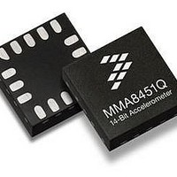
MMA8452QR1 Freescale Semiconductor, MMA8452QR1 Datasheet - Page 42

MMA8452QR1
Manufacturer Part Number
MMA8452QR1
Description
Board Mount Accelerometers LOW G 3-AXIS 12BT EX VLT
Manufacturer
Freescale Semiconductor
Specifications of MMA8452QR1
Sensing Axis
X, Y, Z
Acceleration
2 g, 4 g, 8 g
Digital Output - Number Of Bits
8 bit, 12 bit
Supply Voltage (max)
3.6 V
Supply Voltage (min)
1.95 V
Maximum Operating Temperature
+ 85 C
Minimum Operating Temperature
- 40 C
Digital Output - Bus Interface
I2C
Shutdown
Yes
Sensitivity
256 count/g, 512 count/g, 1024 count/g
Package / Case
QFN-16
Output Type
Digital
Rohs Compliant
Yes
Peak Reflow Compatible (260 C)
Yes
Acceleration Range
± 2g, ± 4g, ± 8g
No. Of Axes
3
Ic Interface Type
I2C
Sensor Case Style
QFN
No. Of Pins
16
Supply Voltage Range
1.95V To 3.6V
Lead Free Status / RoHS Status
Lead free / RoHS Compliant
Available stocks
Company
Part Number
Manufacturer
Quantity
Price
Company:
Part Number:
MMA8452QR1
Manufacturer:
FTDI
Quantity:
1 200
Company:
Part Number:
MMA8452QR1
Manufacturer:
FREESCAL
Quantity:
5 963
Company:
Part Number:
MMA8452QR1
Manufacturer:
FREESCAL
Quantity:
1 000
Part Number:
MMA8452QR1
Manufacturer:
NXP/恩智浦
Quantity:
20 000
0x2B: CTRL_REG2 System Control 2 Register
ST bit activates the self-test function. When ST is set, X, Y, and Z outputs will shift. RST bit is used to activate the software reset.
The reset mechanism can be enabled in STANDBY and ACTIVE mode.
resets the device, no matter whether it is in ACTIVE/WAKE, ACTIVE/SLEEP, or STANDBY mode.
available in both WAKE Mode MOD[1:0] and also in the SLEEP Mode SMOD[1:0].
Table 57. CTRL_REG2 Description
42
0x2B CTRL_REG2 Register (Read/Write)
MMA8452Q
When the reset bit is enabled, all registers are rest and are loaded with default values. Writing ‘1’ to the RST bit immediately
The I
At the end of the boot process the RST bit is de-asserted to 0. Reading this bit will return a value of zero.
The (S)MODS[1:0] bits select which Oversampling mode is to be used shown in
SMODS[1:0]
MODS[1:0]
Bit 7
SLPE
ST
RST
ST
2
Table 59. MODS Oversampling Modes Current Consumption and Averaging Values at each ODR
C communication system is reset to avoid accidental corrupted data access.
1.56 Hz
6.25 Hz
12.5 Hz
100 Hz
200 Hz
400 Hz
800 Hz
Mode
50 Hz
ODR
Self-Test Enable. Default value: 0.
0: Self-Test disabled; 1: Self-Test enabled
Software Reset. Default value: 0.
0: Device reset disabled; 1: Device reset enabled.
SLEEP mode power scheme selection. Default value: 00.
See
Auto-SLEEP enable. Default value: 0.
0: Auto-SLEEP is not enabled;
1: Auto-SLEEP is enabled.
ACTIVE mode power scheme selection. Default value: 00.
See
Current
Bit 6
RST
Table 58
Table 58
165
165
24
24
24
24
44
85
Normal (00)
μ
A
and
and
Table 58. MODS Oversampling Modes
OS Ratio
Table 59
Table 59
(S)MODS1
128
32
16
Bit 5
4
4
4
4
2
0
0
0
1
1
Low Noise Low Power (01)
Current
165
165
24
44
85
8
8
8
SMODS1
Bit 4
μ
(S)MODS0
A
0
1
0
1
OS Ratio
32
8
4
4
4
4
4
2
SMODS0
Bit 3
Current
Low Noise Low Power
High Resolution (10)
High Resolution
165
165
165
165
165
165
165
165
Power Mode
Low Power
Normal
μ
A
Table
OS Ratio
SLPE
Bit 2
1024
256
128
32
16
8
4
2
58. The Oversampling modes are
Current
165
MODS1
Low Power (11)
14
24
44
85
6
6
6
Bit 1
Freescale Semiconductor
μ
A
OS Ratio
16
4
2
2
2
2
2
2
MODS0
Bit 0
Sensors


