PVG3A103C01R00 Murata, PVG3A103C01R00 Datasheet - Page 52
PVG3A103C01R00
Manufacturer Part Number
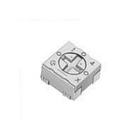
PVG3A103C01R00
Description
Trimmer Resistors - SMD 10Kohms Sealed 3mm Single turn
Manufacturer
Murata
Series
PVG3Ar
Type
Trimmerr
Datasheet
1.PVG3A103C01R00.pdf
(59 pages)
Specifications of PVG3A103C01R00
Resistance
10 KOhms
Power Rating
0.25 Watt (1/4 Watt)
Operating Temperature Range
- 55 C to + 125 C
Element Type
Cermet
Dimensions
3.4 mm W x 3.6 mm L x 2 mm H
Product
Single-Turn Trimmer Potentiometers
Termination Style
SMD/SMT
Tolerance
20 %
Number Of Turns
1
Taper
Linear
Temperature Coefficient
+/- 150 PPM / C
Tolerance (+ Or -)
20%
Technology
Cermet
Mounting Style
Surface Mount
Operating Temp Range
-55C to 125C
Failure Rate
Not Required
Shaft Diameter (mm)
2.2mm
Product Diameter (mm)
Not Requiredmm
Product Length (mm)
3.6mm
Product Height (mm)
2mm
Product Depth (mm)
3.6mm
Lead Free Status / RoHS Status
Lead free / RoHS Compliant
Available stocks
Company
Part Number
Manufacturer
Quantity
Price
Company:

Part Number:
PVG3A103C01R00
Manufacturer:
MURATA
Quantity:
240 000


8
!Note
• This PDF catalog is downloaded from the website of Murata Manufacturing co., ltd. Therefore, it’s specifications are subject to change or our products in it may be discontinued without advance notice. Please check with our
• This PDF catalog has only typical specifications because there is no space for detailed specifications. Therefore, please approve our product specifications or transact the approval sheet for product specifications before ordering.
sales representatives or product engineers before ordering.
!Note
1
50
No.
10
11
12
SMD Sealed Type (PVF2/G3/M4A_D01/G5)/Lead Sealed Type (PV32/12/37/36) Specifications and Test Methods
6
7
8
9
Specifications and Test Methods
Continued from the preceding page.
Temperature Cycle
Humidity
Vibration
Shock
Temperature Road Life
High Temperature Exposure
(Except for PVF2)
Low Temperature Exposure
(Except for PVF2 and
PVM4A---D01)
• Please read rating and !CAUTION (for storage, operating, rating, soldering, mounting and handling) in this catalog to prevent smoking and/or burning, etc.
• This catalog has only typical specifications because there is no space for detailed specifications. Therefore, please approve our product specifications or transact the approval sheet for product specifications before ordering.
Item
The trimmer potentiometer should be subjected to Table 4 temperature for 5 cycles. The trimmer potentiometer
should be removed from the chamber, and maintained at a temperature of 25±5°C for 1-2 hours.
1) PV12, PV32, PVM4A---D01 series
The trimmer potentiometer should be placed in a chamber at a temperature of 40±2°C and a humidity of 90-95%
without loading for 250±8 hours (500±12 hours for PVM4A---D01 series). The trimmer potentiometer should be
removed from the chamber, and maintained at a temperature of 25±5°C for 5±1/6 hours.
2) PVF2 series
The trimmer potentiometer should be placed in a chamber at 60±2°C and 90-95% without loading for 1000±12
hours. The trimmer potentiometer should be removed from the chamber, and maintained at a temperature of 25±5°C
for 5±1/6 hours
2) PVG3, PVG5, PV36, PV37 series
The trimmer potentiometer should be subjected to the programmed humidity environment for 10cycle (see Figure 3).
The trimmer potentiometer should be removed from the chamber, and maintained at a temperature of 25±5°C for
1.5±1/2 hours.
1) PV-- series
The trimmer potentiometer should be vibrated throughout the frequency range at the 20G level. A complete frequen-
cy range, 10Hz to 2000Hz and back, should be made within 15 minutes for a total of 4 sweeps in each of the three
axis directions for a total of 12 sweeps.
2) PVF2 series
The trimmer potentiometer should be subjected to vibration at 0.3 inch amplitude. The frequency should be varied
uniformly between the approximate limits of 10Hz and 55Hz. This motion should be applied for period of 2 hours in
each of 3 mutually perpendicular directions (total of 6 hours).
1) PV-- series
The trimmer potentiometer should be shocked at the 100G level and should be subjected to 4 shocks in each of the
three axis directions for a total of 12 shocks.
2) PVM4A---D01 series
The trimmer potentiometer should be shocked at the 100G level and should be subjected to 3 shocks in each of the
six axis directions for a total of 18 shocks.
Full rated continuous working voltage not exceeding the maximum rated voltage should be applied intermittently
between terminal #1 and terminal #3 of the trimmer potentiometer, 1.5 hours on and 0.5 hours off, for a total of
1000±12 hours, at a temperature of 70±2°C (85±2°C for PV37 series, 50±2°C for PVF2 series). The trimmer
potentiometer should be removed from the chamber, and maintained at a temperature of 25±5°C for 1 to 2 hours.
The trimmer potentiometer should be placed in a chamber at a temperature of 125±3°C 250±8 hours without load-
ing. The trimmer potentiometer should be removed from the chamber, and maintained at a temperature of 25±5°C
for 1 to 2 hours.
The trimmer potentiometer should be placed in a chamber at a temperature of -55±3°C for 1 hours without loading.
Full rated continuous working voltage not exceeding the maximum rated voltage should be applied for 45 minutes.
The trimmer potentiometer should be removed from the chamber, and maintained at a temperature of 25±5°C for
approximately 24 hours.
Temp.
(°C)
Time (min.)
Sequence
-10
70
65
60
55
50
45
40
35
30
25
20
15
10
-5
Table 4: One cycle of temperature cycle.
5
0
PV-- series
PVF2 series
INITIAL CONDITIONING
IN A DRY OVEN
HUMIDITY
UNCONTROLLED
INITIAL MEASUREMENTS
AS SPECIFIED IN 3.2
UNLESS OTHERWISE SPECIFIED
TEMPERATURE TOLERANCE IS,
CHAMBER EXCEPT THE IMMEDIATE
VICINITY OF THE SPECIMENS AND
THE CHAMBER SURFACES
2 C AT ALL POINTS WITHIN THE
PRIOR TO FIRST CYCLE
UNLESS OTHERWISE
SPECIFIED
24 HOURS
-55±3
-25±3
30
1
0
5 max.
+25±2
STEP 1
1
2
90-98%RH
RATE OF CHANGE OF TEMPERATURE IS UNSPECIFIED.
HOWEVER, SPECIMENS SHOULD NOT BE SUBJECTED
TO RADIANT HEAT FROM CHAMBER-CONDITIONING
PROCESSES
2
VOLTAGE APPLIED AS SPECIFIED IN 3.5
3
STEP 2
+125±3
+60±3
CIRCULATION OF CONDITIONING AIR SHOULD
BE AT A MINIMUM CUBIC RATE PER MINUTE
EQUIVALENT TO 5 TIMES THE VOLUME OF
THE CHAMBER
4
30
3
5
STEPS 7a AND 7b PERFORMED DURING ANY
5 OF THE FIRST 9 CYCLES. HUMIDITY
UNCONTROLLED DURING STEPS 7a AND 7b
ONLY
ONE CYCLE 24 HOURS. REPEAT AS SPECIFIED IN 3.3
80-98%RH
STEP 3
6
Figure 3
5 max.
+25±2
7
Test Methods
4
8
STEP 4
+10 C
9
-2 C
90-98%RH
10
11
STEP 5
12
13
80-98%RH
14
STEP 6
15
16
17
MIL-STD-202 METHOD 106
18
STEP 7a
END OF FINAL CYCLE
MEASUREMENTS AS
SPECIFIED IN 3.6
90-98%RH
19
STEP 7
Continued on the following page.
20
21
22 23 24
STEP 7b
R50E.pdf
08.8.26
Related parts for PVG3A103C01R00
Image
Part Number
Description
Manufacturer
Datasheet
Request
R

Part Number:
Description:
Murata Microblower 20x20 DCDC Driver Board - Samples Only
Manufacturer:
Murata
Part Number:
Description:
357-036-542-201 CARDEDGE 36POS DL .156 BLK LOPRO
Manufacturer:
Murata
Datasheet:
Part Number:
Description:
Manufacturer:
Murata
Datasheet:
Part Number:
Description:
Manufacturer:
Murata
Datasheet:
Part Number:
Description:
Manufacturer:
Murata
Datasheet:
Part Number:
Description:
Manufacturer:
Murata
Datasheet:
Part Number:
Description:
Manufacturer:
Murata
Datasheet:
Part Number:
Description:
Manufacturer:
Murata
Datasheet:
Part Number:
Description:
Manufacturer:
Murata
Datasheet:
Part Number:
Description:
BLM21BD751SN1On-Board Type (DC) EMI Suppression Filters
Manufacturer:
Murata
Datasheet:
Part Number:
Description:
BLM15AG100SN1On-Board Type (DC) EMI Suppression Filters
Manufacturer:
Murata
Datasheet:
Part Number:
Description:
NFE31PT222Z1E9On-Board Type (DC) EMI Suppression Filters
Manufacturer:
Murata
Datasheet:
Part Number:
Description:
Chip Coil
Manufacturer:
Murata
Datasheet:
Part Number:
Description:
Chip Coil
Manufacturer:
Murata
Datasheet: