MKS3PI-5 DC24 Omron, MKS3PI-5 DC24 Datasheet

General Purpose / Industrial Relays Basic 3PDT 24 VDC Std w/Lock Button

MKS3PI-5 DC24

Manufacturer Part Number
MKS3PI-5 DC24
Description
General Purpose / Industrial Relays Basic 3PDT 24 VDC Std w/Lock Button
Manufacturer
Omron
Series
MKSr
Datasheets

Specifications of MKS3PI-5 DC24

Coil Resistance
430 Ohms
Contact Form
3PDT
Coil Voltage
24 VDC
Contact Rating
10 A
Contact Termination
Quick Connect
Mounting Style
Plug-In
Power Consumption
1.4 W
Contact Material
Silver Alloy
Coil Current
55.8 mA
Relay Type
General Purpose
Coil Voltage Vdc Nom
24V
Contact Current Max
10A
Contact Voltage Ac Nom
250V
Contact Voltage Dc Nom
30V
Contact Configuration
3PDT
Contact Rating (current)
10A
Switching Voltage
250VAC, 30VDC - Max
Coil Type
Non Latching
Turn On Voltage (max)
19.2 VDC
Turn Off Voltage (min)
3.6 VDC
Features
Mechanical Indicator, Test Button
Mounting Type
Socketable
Termination Style
Plug In, 11 Pin (Octal)
Operate Time
30ms
Release Time
20ms
Coil Power
1.4 W
Operating Temperature
-40°C ~ 60°C
Lead Free Status / RoHS Status
Lead free / RoHS Compliant
Lead Free Status / RoHS Status
Lead free / RoHS Compliant, Lead free / RoHS Compliant
New Super MK Relays.
Models with Latching Lever Added to
the Series.
Features
Models with Latching Lever
Operation indicator *
Nameplate
Mechanical indicator
Latching lever
* The operation indicator is built in only on specified models.
Example of Applications of Models with Latching
Levers
Operation checks in relay sequence circuits
Model Number Structure
Model Number Legend
1. Contact Form
2. Terminals
3. Mechanical Indicator/Test Button
4. LED Indicator
MKS@@@@@-@-@
• Same mounting and internal wiring as the previous Super
• Built-in mechanical indicator enables checking contact
• Two modes can be used to check circuits for models with
• Nameplate provided on models with latching lever.
• All materials are RoHS compliant.
• UL and IEC (TÜV) certification.
DC: Blue
AC: Red
General-purpose Relays
MK-S
MK Relays
operation.
latching lever.
2: DPDT
3: 3PDT
P: Plug-in
Blank: Mechanical indicator
I:
Blank: Standard
N:
1 2 3 4 5
Mechanical indicator and lockable test button
LED indicator
6
7
(New Models)
Normal Operation
Operating Method for Latching Lever
5. Coil Polarity
6. Surge Absorption
7. Internal Connections
8. Rated Voltage
Blank: Standard
1:
Blank: Standard
D:
V:
Blank: Standard
2 or 5: Non-standard connections (Refer to “Terminal
(Refer to “Coil Ratings”.)
Relay in
Reverse polarity (DC coil only)
Surge absorber diode (DC coil only)
Surge absorber varistor (AC coil only)
Arrangement and Internal Connection (Bottom View)”.)
Yellow
button
Slide the latching lever
to the first position,
then press the yellow
button with an
insulated tool to
operate the contact.
For Momentary
Operation
CSM_MK-S_DS_E_6_1
Slide the latching
lever to the second
position.
(The contact is now in
the locked position.)
Operation
For Lock
1

MKS3PI-5 DC24 Summary of contents

Page 1

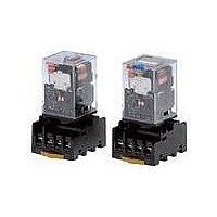
General-purpose Relays MK-S (New Models) New Super MK Relays. Models with Latching Lever Added to the Series. • Same mounting and internal wiring as the previous Super MK Relays • Built-in mechanical indicator enables checking contact operation. • Two modes ...

Page 2

... Coil ratings and lockable test button MKS2PI MKS2PI-2 MKS3PI AC/DC MKS3PI-2 MKS3PI-5 MKS2PIN(1) MKS2PIN(1)-2 MKS3PIN(1) AC/DC MKS3PIN(1)-2 MKS3PIN(1)-5 MKS2PI(1)-D MKS2PI(1)-D-2 MKS3PI(1)-D DC MKS3PI(1)-D-2 MKS3PI(1)-D-5 MKS2PIN-D MKS2PIN-D-2 MKS3PIN-D DC MKS3PIN-D-2 MKS3PIN-D-5 MKS2PI-V MKS2PI-V-2 MKS3PI-V AC MKS3PI-V-2 MKS3PI-V-5 MKS2PIN-V MKS2PIN-V-2 MKS3PIN-V AC MKS3PIN-V-2 MKS3PIN-V-5 2 ...

Page 3

Specifications Ratings Coil Ratings Rated current Rated voltage 443 mA 385 221 mA 193 110 mA 96.3 mA 100 V 26 110 V 24.2 ...

Page 4

Characteristics Contact resistance 100 mΩ max. AC max. Operate time DC max. Release time 20 ms max. (40 ms max. for built-in Diode Relays) Mechanical: 18,000 operations/h Max. operating frequency Electrical: Insulation resistance 100 MΩ min. ...

Page 5

Dimensions Models without Latching Lever 34.5 max. 34.5 max. 0.8 52.5 max. Sockets See below for Socket dimensions. Surface-mounting Socket (for track or screw mounting) Socket Finger-protection models Maximum carry 10 A current PF083A-E 2 poles PF113A-E 3 poles Note: ...

Page 6

PF083A Eight, M4 screws 65 38 Hold-down Clips PFC-A1 (2 pieces per set) 4.6 60 4.5 Mounting Tracks PFP-100N, PFP-50N (Conforming to EN 50022) 7.3±0.15 4 ...

Page 7

Terminal Arrangement and Internal Connection (Bottom View) Standard Models MKS2P(I) (AC/DC Coil Models with MKS2P(I)N LED Indicator 4 5 (AC Coil Models with Diode MKS2P(I)N (DC Coil Standard ...

Page 8

Models with Varistor MKS2P(I)-V (AC Coil Models with MKS2P(I)N-V LED indicator and 4 5 Varistor 3 (AC Coil Safety Precautions Refer to Safety Precautions for All Relays. Safety Precautions for Correct ...

Page 9

... Please read and understand this catalog before purchasing the products. Please consult your OMRON representative if you have any questions or comments. WARRANTY OMRON's exclusive warranty is that the products are free from defects in materials and workmanship for a period of one year (or other period if specified) from date of sale by OMRON. OMRON MAKES NO WARRANTY OR REPRESENTATION, EXPRESS OR IMPLIED, REGARDING NON-INFRINGEMENT, MERCHANTABILITY, OR FITNESS FOR PARTICULAR PURPOSE OF THE PRODUCTS ...