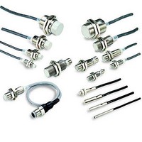
E2E-X1B1 Omron, E2E-X1B1 Datasheet - Page 23

E2E-X1B1
Manufacturer Part Number
E2E-X1B1
Description
Proximity Sensors INDUCTIVE M5 PNP OUT
Manufacturer
Omron
Type
Inductive Proximity Sensorr
Series
E2E3r
Datasheet
1.E2E2-X5MB1-M1.pdf
(48 pages)
Specifications of E2E-X1B1
Maximum Operating Temperature
+ 70 C
Supply Voltage
30 V
Operating Supply Voltage
10 V to 30 V
Minimum Operating Temperature
- 25 C
Maximum Output Current
100 mA
Features
High visibility indicator
Sensing Distance
1 mm
Sensor Input
Inductive
Sensing Range
1mm
Supply Voltage Range Dc
10V To 30V
Mounting Type
Panel
Switch Terminals
Cable
Load Current Rms Max
100mA
Sensing Face Diameter
5mm
Supply Voltage Min
10VDC
Sensor Type
Inductive
Sensing Object
Metallic
Response Frequency
3kHz
Material - Body
Nickel-Plated Brass
Shielding
Shielded
Voltage - Supply
10 V ~ 30 V
Output Type
PNP-NO
Terminal Type
3-Wire
Package / Case
Cylinder, Threaded - M5
Rohs Compliant
Yes
Lead Free Status / RoHS Status
Lead free / RoHS Compliant
Lead Free Status / RoHS Status
Lead free / RoHS Compliant, Lead free / RoHS Compliant
Available stocks
Company
Part Number
Manufacturer
Quantity
Price
Company:
Part Number:
E2E-X1B1
Manufacturer:
VISHAY
Quantity:
7 590
Output Circuits and Timing Charts
■ Output Circuits
E2E
E2E-X@D@ DC 2-wire Models
DC 3-wire Models
E2E-X@D1
Without Diagnostic Output
E2E-X@E@
NPN Output
E2E-C/X@C@
NPN Open-collector Output
Note: 1. The load can be connected to
Note: 1. The load can be connected to
E2E-X@D2
Without Diagnostic Output
Proximity
sensor
main
circuit
Proximity
sensor
main
circuit
2. The pin numbers in the above
2. The pin numbers in the above diagram
either the +V or 0 V side.
either the +V or 0 V side.
diagram are for the -M@G.
For -M1 models, pin 2 is +V
and pin 3 is 0 V.
are for the -M@G(J). For the -M1, pin 4
is +V and pin 3 is 0 V.
* Constant current output is 1.5 to 3 mA.
** Pin 4 is an NO contact, and pin 2 is an NC contact.
* E2E-CR6@ has no 100-Ω resistance.
Proximity
sensor
main
circuit
Proximity
sensor
main
circuit
100 Ω
100 Ω
Constant
current*
1
1
Brown
4
Brown
2
Blue
Blue
Load
Load
Brown 1
Black 4
Output
Blue 3
Black 4
(or 2)**
Blue 3
Brown 1
0 V
0 V
Load
Load
Note: 1. The load can be connected to
E2E-X@D1-M1J-T
No Polarity
0 V
Proximity
sensor
main
circuit
0 V
2. The E2E-X@D1-M1J-T has no
either the +V or 0 V side.
polarity. Therefore, terminals 3
and 4 have no polarity.
E2E-X@F@
PNP Output
E2E-C/X@B@
PNP Open-collector Output
E2E/E2E2
4
3
Load
Proximity
sensor
main
circuit
Proximity
sensor
main
circuit
* E2E-CR6@ has no 100-Ω resistance.
*** Pin 4 is an NO contact, and pin 2 is an NC contact.
* Constant current output is 1.5 to 3 mA.
** When connecting to a Tr circuit.
(0 V)
0 V
*
100 Ω
E2E-X@D1S
With Diagnostic Output
100 Ω
Cylindrical Proximity Sensor
Note: Connect both the loads to the +V
Proximity
sensor
main
circuit
side of the control output and
diagnostic output.
Black 4
(or 2)***
Brown 1
Blue 3
Brown 1
Black 4
Blue 3
**
Load
Load
0 V
0 V
4
2
Brown
Orange (diagnostic
output)
Blue 3
Load
Load
0 V
23


