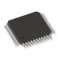
PIC18F45K80-I/PT Microchip Technology, PIC18F45K80-I/PT Datasheet - Page 51

PIC18F45K80-I/PT
Manufacturer Part Number
PIC18F45K80-I/PT
Description
MCU PIC 32KB FLASH 44TQFP
Manufacturer
Microchip Technology
Series
PIC® XLP™ 18Fr
Datasheet
1.PIC18F25K80-ISO.pdf
(628 pages)
Specifications of PIC18F45K80-I/PT
Core Size
8-Bit
Program Memory Size
32KB (16K x 16)
Peripherals
Brown-out Detect/Reset, LVD, POR, PWM, WDT
Core Processor
PIC
Speed
64MHz
Connectivity
ECAN, I²C, LIN, SPI, UART/USART
Number Of I /o
35
Program Memory Type
FLASH
Eeprom Size
1K x 8
Ram Size
3.6K x 8
Voltage - Supply (vcc/vdd)
1.8 V ~ 5.5 V
Data Converters
A/D 11x12b
Oscillator Type
Internal
Operating Temperature
-40°C ~ 85°C
Package / Case
44-TQFP
Controller Family/series
PIC18
Ram Memory Size
4KB
Cpu Speed
16MIPS
No. Of Pwm Channels
5
Embedded Interface Type
I2C, SPI, USART
Processor Series
PIC18F45K80
Core
PIC
Data Bus Width
8 bit
Data Ram Size
1 KB
Interface Type
I2C, SPI, USART
Maximum Clock Frequency
64 MHz
Number Of Programmable I/os
35
Number Of Timers
5
Operating Supply Voltage
1.8 V to 5.5 V
Maximum Operating Temperature
+ 85 C
Mounting Style
SMD/SMT
Lead Free Status / RoHS Status
Lead free / RoHS Compliant
Lead Free Status / RoHS Status
Lead free / RoHS Compliant
Available stocks
Company
Part Number
Manufacturer
Quantity
Price
Company:
Part Number:
PIC18F45K80-I/PT
Manufacturer:
MICROCHIP
Quantity:
1 500
Company:
Part Number:
PIC18F45K80-I/PT
Manufacturer:
PIC
Quantity:
400
Company:
Part Number:
PIC18F45K80-I/PT
Manufacturer:
Microchip Technology
Quantity:
10 000
Part Number:
PIC18F45K80-I/PT
Manufacturer:
MICROCHIP/微芯
Quantity:
20 000
- Current page: 51 of 628
- Download datasheet (6Mb)
In planning the application’s routing and I/O assign-
ments, ensure that adjacent port pins and other signals
in close proximity to the oscillator are benign (i.e., free
of high frequencies, short rise and fall times, and other
similar noise).
For additional information and design guidance on
oscillator circuits, please refer to these Microchip
Application Notes, available at the corporate web site
(www.microchip.com):
• AN826, “Crystal Oscillator Basics and Crystal
• AN849, “Basic PICmicro
• AN943, “Practical PICmicro
• AN949, “Making Your Oscillator Work”
2.7
Unused I/O pins should be configured as outputs and
driven to a logic low state. Alternatively, connect a 1 kΩ
to 10 kΩ resistor to V
output to logic low.
2011 Microchip Technology Inc.
Selection for rfPIC™ and PICmicro
and Design”
Unused I/Os
SS
on unused pins and drive the
®
Oscillator Design”
®
Oscillator Analysis
®
Devices”
Preliminary
PIC18F66K80 FAMILY
FIGURE 2-4:
(tied to ground)
Timer1 Oscillator
Bottom Layer
Copper Pour
Oscillator
GND
Primary
Crystal
OSCO
OSCI
C1
C2
T1 Oscillator: C1
DEVICE PINS
Single-Sided and In-Line Layouts:
Fine-Pitch (Dual-Sided) Layouts:
(tied to ground)
Copper Pour
SUGGESTED PLACEMENT
OF THE OSCILLATOR
CIRCUIT
Top Layer Copper Pour
`
`
(tied to ground)
`
Primary Oscillator
T1 Oscillator: C2
Crystal
DEVICE PINS
DS39977C-page 51
C2
C1
Oscillator
Crystal
OSC1
OSC2
GND
T1OSO
T1OS I
Related parts for PIC18F45K80-I/PT
Image
Part Number
Description
Manufacturer
Datasheet
Request
R

Part Number:
Description:
Manufacturer:
Microchip Technology Inc.
Datasheet:

Part Number:
Description:
Manufacturer:
Microchip Technology Inc.
Datasheet:

Part Number:
Description:
Manufacturer:
Microchip Technology Inc.
Datasheet:

Part Number:
Description:
Manufacturer:
Microchip Technology Inc.
Datasheet:

Part Number:
Description:
Manufacturer:
Microchip Technology Inc.
Datasheet:

Part Number:
Description:
Manufacturer:
Microchip Technology Inc.
Datasheet:

Part Number:
Description:
Manufacturer:
Microchip Technology Inc.
Datasheet:

Part Number:
Description:
Manufacturer:
Microchip Technology Inc.
Datasheet:


